>
Technical note
9 Min read
Application of the Giroud–Han design method for geosynthetic reinforced unpaved roads with MIRAFI geosynthetics
Unpaved road design using MIRAFI geosynthetics
MIRAFI® geosynthetics have been used and designed in unpaved road projects since the 1970’s1 and into paved roadway applications since the 1980’s2. MIRAFI geosynthetics are used in roadways to reduce construction time, construction materials, construction costs, and to increase the usable life of the roadway. The benefits that geosynthetics provide in roadway construction are well documented. The United States Department of Transportation Federal Highway Administration (FHWA) offers their expert guidance on the benefits of using geosynthetic in roadways: “Geosynthetics have been found to provide significant improvement in pavement construction and performance… The most common of all uses of geosynthetics is in road and pavement construction. Geotextiles placed at the subgrade increase stability and improve performance of pavement constructed on high fines subgrade soils (i.e., soils containing high quantities of silt and/or clay particles)…”. 3
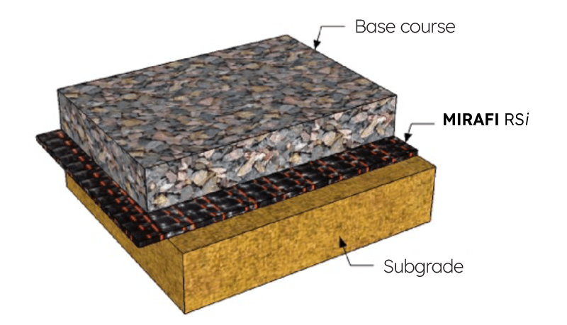
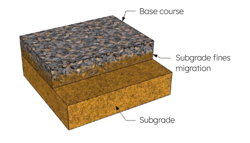
Using a geotextile keeps the subgrade and gravel layers from intermixing, thus keeping the structural integrity of the roadway intact. Further, an estimated 80% of all roads in the United States are unpaved, using only gravel to construct the roadway. According to an American Association of State Highway and Transportation Officials (AASHTO) report, approximately 20% of roadways fail due to insufficient structural strength.
For unpaved road and subgrade stabilization design, the Giroud-Han (G-H) design method developed an equation that is used to calculate the required thickness of graded aggregate. Publication of the design method in 20048,9 in the ASCE Journal of Geotechnical and Geoenvironmental Engineering culminated after several years of research, dating back to the Giroud-Noiray study published in 198110. The G-H design equation has also been referenced in the “Geosynthetic Design and Construction Guidelines” manual by the Federal Highway Administration3. It is one of the most recognized and widely accepted methods for determining the structural contribution of both geotextiles and geogrids in aggregate-only based roadways.
The G-H design method uses a generic iterative equation that can be implemented for both unreinforced and geosynthetic reinforced gravel roadways:
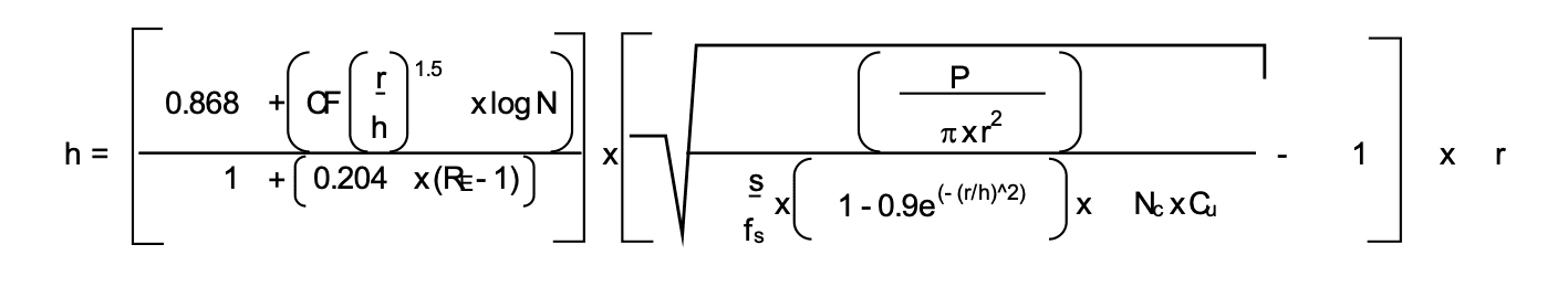
Where:
h = required compacted aggregate (gravel) thickness (m);
CF = calibration factor for the geosynthetic used in design (= {0.6611.006J2} for punched and drawn biaxial geogrids);
N = the number of axle passes;
RE = limited modulus ratio of compacted aggregate to subgrade soil (maximum = 5.0);
P = wheel load (kN);
fs = reference rut depth (75 mm);
r = radius of the equivalent tire contact area (m);
s = allowable rut depth (mm; for rut depths between 50 mm and 100 mm);
Nc = bearing capacity factor (3.14 for unreinforced; 5.14 for geotextile reinforced; 5.71 for geogrid reinforced);
Cu = undrained shear strength of subgrade (taken as 30 kPa x CBR of the subgrade soil for CBR’s between 1% and 5%);
P/πr2 = tire contact pressure (kPa), and is equivalent to the tire pressure (p).
It is important to note that the design method has been calibrated by Giroud-Han for surface rutting between 50 mm (2”) and 100 mm (4”) and for subgrade strengths between 30 kPa (CBR = 1%) and 150 kPa (CBR = 5%)8,9 and for a compacted aggregate layer strength of 600 kPa (CBR = 20%).
Determining the calibration factor (CF) for the geosynthetics used in the design procedure requires an extensive calibration for each individual material. The calibration processes can be costly and time consuming since determining the CF for a geosynthetic is also a function of the design variables r, h, RE, P, s and Cu that are derived from comprehensive construction and testing practices. The CF values for MIRAFI geosynthetics were determined through exhaustive calibrations with the G-H design equation following AASHTO13 and FHWA3 guidelines and using large-scale cyclic plate loading testing results. Calibration was performed using a number of subgrade soils and aggregate layers with different thicknesses and strengths.
The applied loading, load frequency, strain levels in the geosynthetics and pore water pressures in the subgrade and aggregate were monitored. The CF values from this extensive testing were established for MIRAFI geosynthetics following the G-H design method calibration work published by Pokharel at the University of Kansas12.
The level of tensile, separation and pore pressure dissipation benefits that MIRAFI RSi-Series and MIRAFI H2Ri woven geotextiles provide is unequaled compared to other geosynthetics. Their superior performance can be attributed to their high tensile moduli at low strains, their enhanced drainage and filtration capacities and their exceptional interaction with roadway soils and aggregates. Choose to use MIRAFI H2Ri over RS580i when your project’s subgrade soils can benefit from its enhanced lateral wicking capacity, pore pressure dissipation and capillary break functions that MIRAFI H2Ri can provide to the roadway.
Table 1, below, shows the exceptional performance of these MIRAFI geosynthetics in the form of an estimated aggregate thickness reduction for an example roadway cross section.
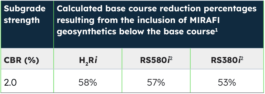
Table 1: Estimated aggregate layer reduction percentages using MIRAFI geosynthetics using the Giroud-Han unpaved road design method.
Notes: 1 Estimates are for 750,000 applied loads, 14 kip wheel load, 110 psi tire pressure, 1.0 inch rut depth, roadway aggregate CBR = 20% and an overall factor of safety of 1.0, rounded to the nearest 0.5 inch. 2 Recommended minimum aggregate layer thickness not less than 6 inches for MIRAFI geosynthetics.
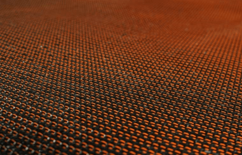
MIRAFI RSi-Series woven geotextile
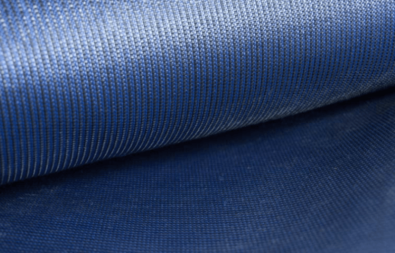
MIRAFI H2Ri-Series woven geotextile
An example design calculation below provides an analysis for the calculated savings in the amount of aggregate needed and related cost savings for a typical unpaved road section over a soft subgrade soil using MIRAFI RS380i and designed with the G-H unpaved road design method.
Example
A section of unpaved road that will support 12,000 axle passes from a 9,000 lb dual wheel load with 100 psi tire pressure is to be constructed on a soft subgrade with a CBR value of 1.6% and the tolerable surface rutting will be 1.5 inches.
Calculate the cost savings per lane mile that results from using MIRAFI RS380i in the roadway cross section, at the subgrade - aggregate layer interface.
Given
Number of axle passes (N) = 12,000
Wheel load (P) = 9,000 lb = 40 kN
Tire pressure = 80 psi = 552 kPa
Surface rutting = 1.5 inch, = 38.1 mm
Subgrade CBR = 1.6%, = 48 kPa = Cu
Geosynthetic Reinforcement is MIRAFI RS380i
Solution
First, calculate the required roadway aggregate thickness without a geosynthetic using the Giroud-Han design method. The bearing capacity Nc factor for an unreinforced subgrade soil is 3.14 (or π) and the CF for an unreinforced roadway is 0.661. Since the solution for “h” requires iteration, meaning one must start with an assumed value for “h” and then the new value of “h” obtained from solving the equation is then input back into the equation to solve for another new value for “h.”
This process is repeated until the difference between the input value of “h” and the solved value of “h” is very small (i.e. the difference is negligible). Using the G-H design equation, the calculated unreinforced thickness “h” = 24 inches (610 mm).
Next, calculate the required thickness of roadway aggregate using MIRAFI RS380i as the geosynthetic reinforcement. The Nc factor for a geotextile using the G-H method is 5.14 (π + 2) and the CF for MIRAFI RS380i for these project parameters is 0.061. The calculated thickness for the roadway using MIRAFI RS380i is 6 inches (152 mm).
Conclusion
The example above shows only the aggregate material savings that can be realized by using MIRAFI RS380i geotextile in an unpaved roadway. Other benefits of MIRAFI RSi-Series and MIRAFI H2Ri geotextiles are construction cost savings in undercut, hauling and labor costs, as well as shortened construction schedules. Long-term savings are realized through increased roadway life and a reduction in maintenance and rehabilitation costs. It’s also very important to note that using MIRAFI RSi and MIRAFI H2Ri series geotextiles will significantly reduce carbon (CO2) emissions in the form of reduced transport (fewer truckloads of aggregate to the site), aggregate processing, and sitework (construction equipment) emissions. Sometimes the use of MIRAFI RSi-Series and MIRAFI H2Ri geotextile makes an otherwise impossible project feasible.
References
Barenberg, E. J., Dowland, James H. Jr., and Hales, John H., “Evaluation of Soil Aggregate Systems with MIRAFI Fabric,” Civil Engineering Studies, Department of Civil Engineering, University of Illinois, 1975
Hamilton, J. M., Pearce, R. A., “Guidelines for Design of Flexible Pavements Using MIRAFI Woven Stabilization Fabrics,” Law Engineering, Houston, TX 1981
US Department of Transportation, Federal Highways Administration, National Highway Institute, Course No. 132013, “Geosynthetic Design and Construction Guidelines Reference Manual, Chapter 5,” Publication No. NHI-06-116, February 2007
Christopher, B. R. and Lacina, B. A., “Roadway Subgrade Stabilization Study”, Proceedings of GeoAmericas 2008, Cancun, Mexico, 2008, International Geosynthetic Society, pp. 1013–1021.
Christopher, B. R., Perkins, S. W., Lacina, B. A., Marr, W. A., “Pore Water Pressure Influence on Geosynthetic Stabilized Subgrade Performance,” Proceedings, 2009 Geosynthetics Conference, Salt Lake City, Utah, February 2009
Perkins, S. W., Christopher, B. R., Lacina, B. A., “Mechanistic-Empirical Design Method for Unpaved Roads Using Geosynthetics,” Proceedings of the 4th European Geosynthetics Conference, Edinburgh, Scotland, Paper No. 228
AASHTO (2006), Standard Specifications for Geotextiles - M 288, Standard Specifications for Transportation Materials and Methods of Sampling and Testing, 26th Edition, American Association of State Transportation and Highway Officials, Washington, D.C.
Giroud, J.P. and Han, J. (2004a), “Design method for geogrid-reinforced unpaved roads-Part I: theoretical development,” ASCE Journal of Geotechnical and Geoenvironmental Engineering, 130(8), pp 776-778.
Giroud, J.P. and Han, J. (2004b), “Design method for geogrid-reinforced unpaved roads-Part II: calibration and verification,” ASCE Journal of Geotechnical and Geoenvironmental Engineering, 130(8), 787-797. 10. Giroud, J.P. and Noiray, L. (1981), “Geotextile-reinforced unpaved road design,” ASCE Journal of Geotechnical and Geoenvironmental Engineering, 107(9), pp 1233-1253.
Kinney, T. C. (2000), Standard test method for determining the ‘‘Aperture Stability Modulus’’ of a geogrid, Shannon & Wilson, Inc., Seattle.
Pokharel, S.K. (2010), “Experimental Study on Geocell – Reinforced Bases under Static and Dynamic Loadings, Ph.D. dissertation", CEAE Department, the University of Kansas, 316p.
AASHTO (2009), Standard Practice for Geosynthetic Reinforcement of the Aggregate Base Course of Flexible Pavement Structures - R 50-09, American Association of State Transportation and Highway Officials, Washington, D.C.