Flood protection for Reinland Drain in Manitoba
PROPEX® Armormax® stabilized the eroded Reinland Drain, reducing costs and emissions while ensuring long-term flood protection with reinforced vegetation growth.
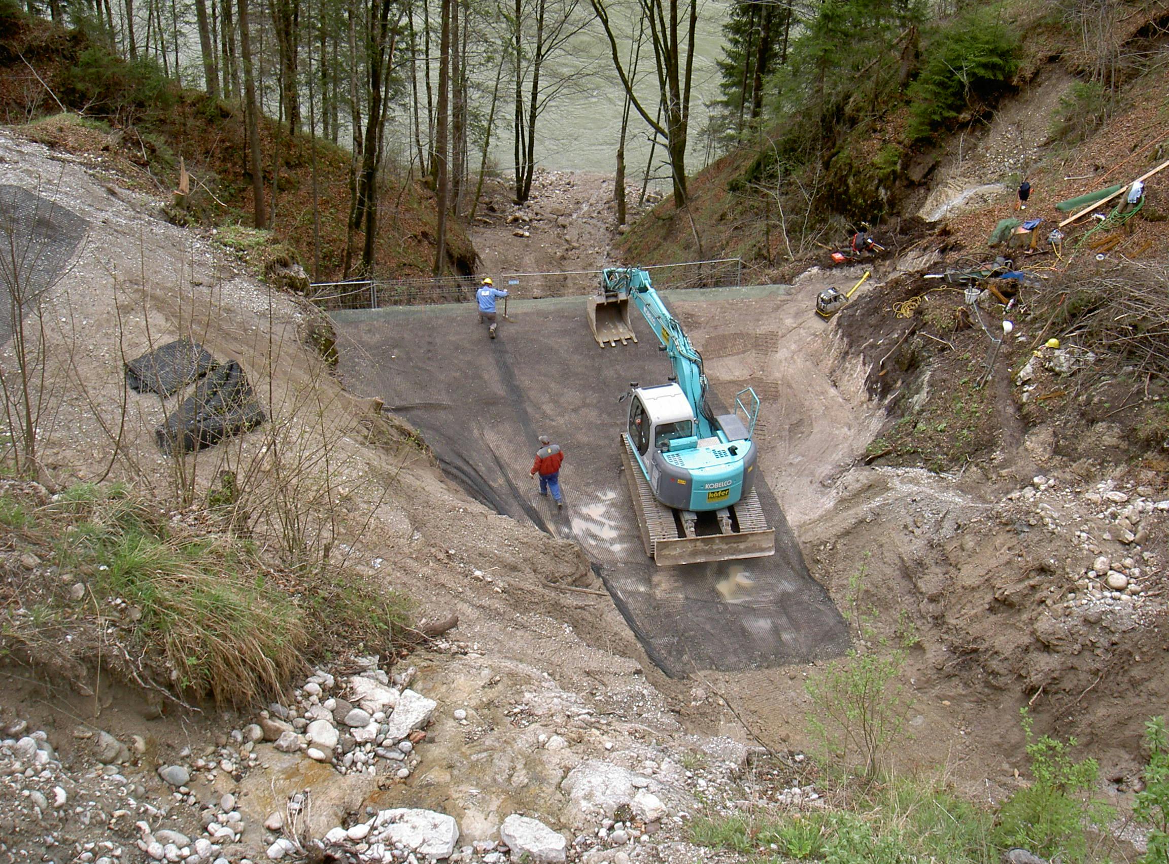
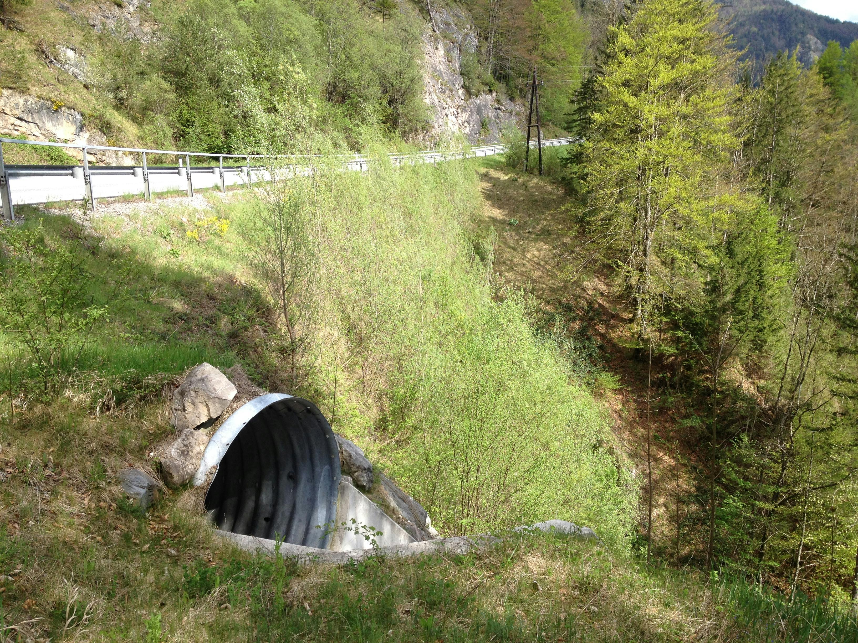
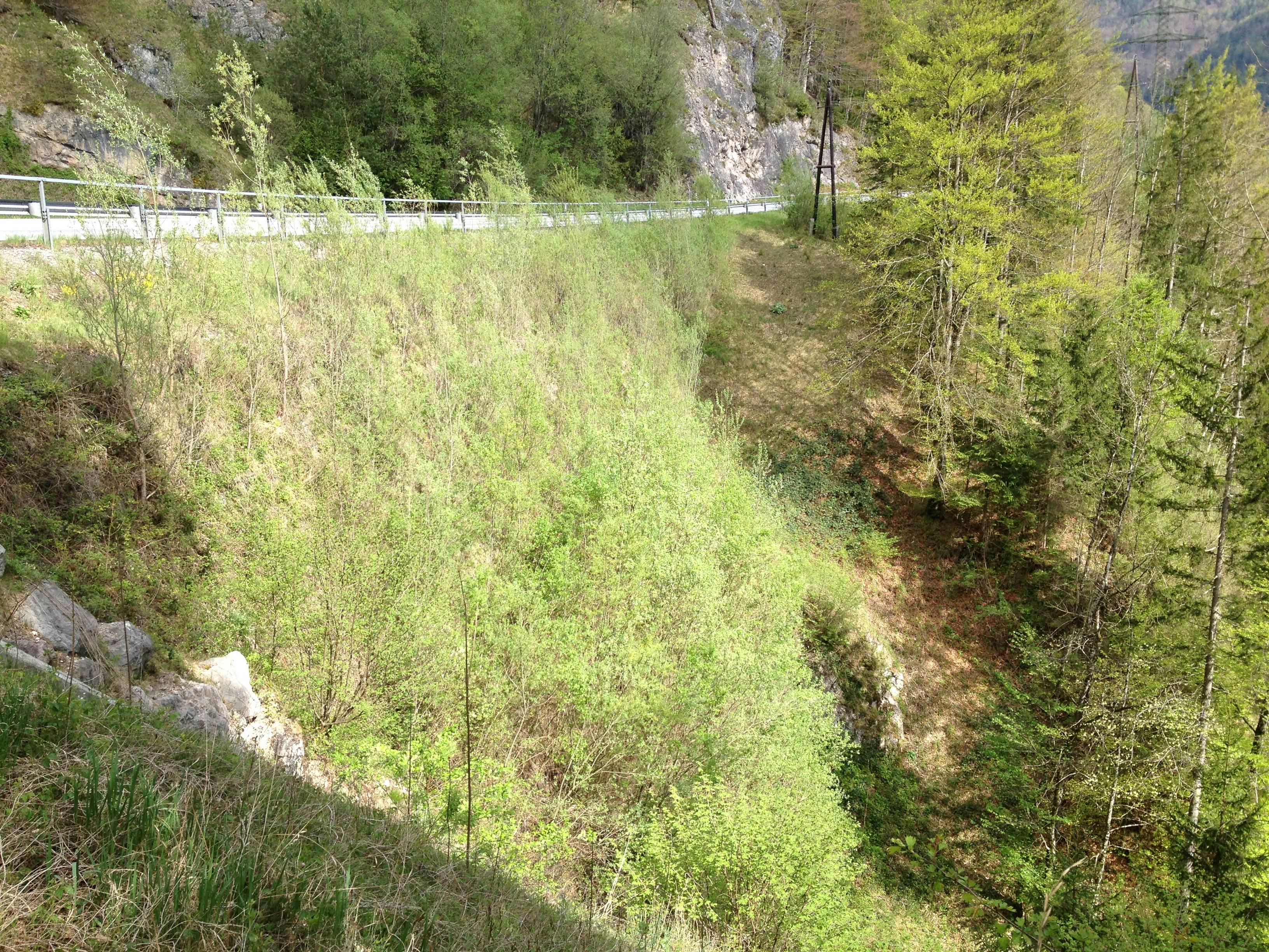
Due to increased traffic loadings and seepage problems, a section of the B115 highway in the mountains of Styria, Austria, was showing considerable distress and was in danger of failure.
The highway is used mainly by heavy trucks hauling timber, and restrictions had to be placed on these vehicles after large deformations were observed in the vicinity of an old 10 m (32.8 ft) high masonry retaining wall. The local authority was under pressure to find a technically viable solution to the problem while keeping within a limited budget.
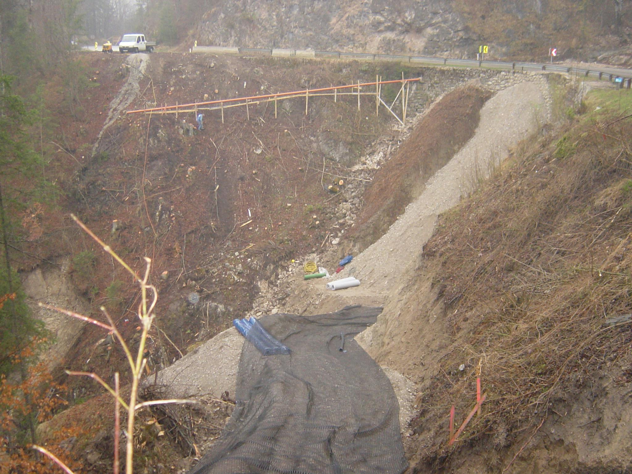
One solution investigated was the provision of a bridge to span across the unstable area, but this was rejected as being too costly. Furthermore, conventional retaining wall solutions were found to be non-viable because of the large height involved (34 m or 111.5 ft) and limited base area available for the wall.
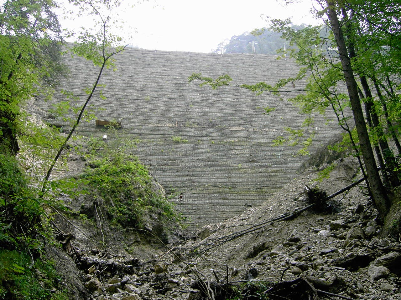
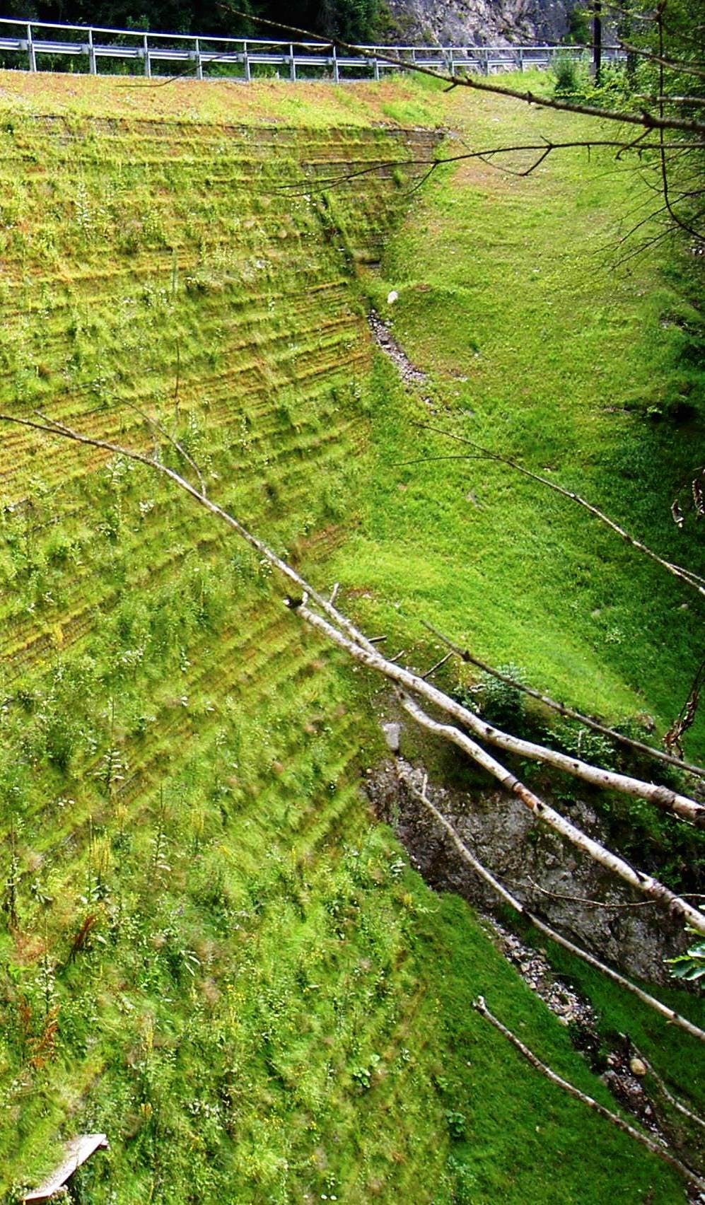
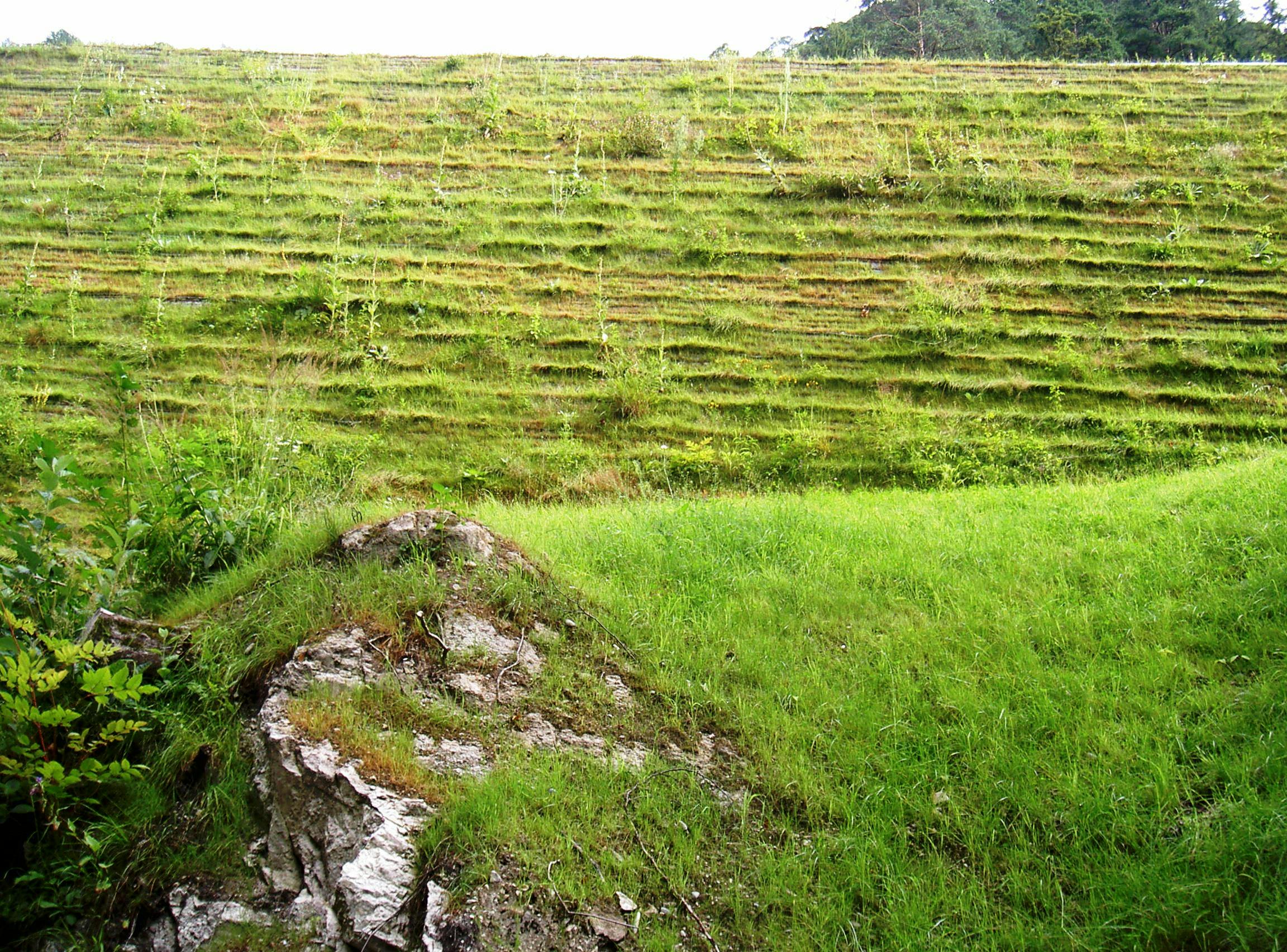
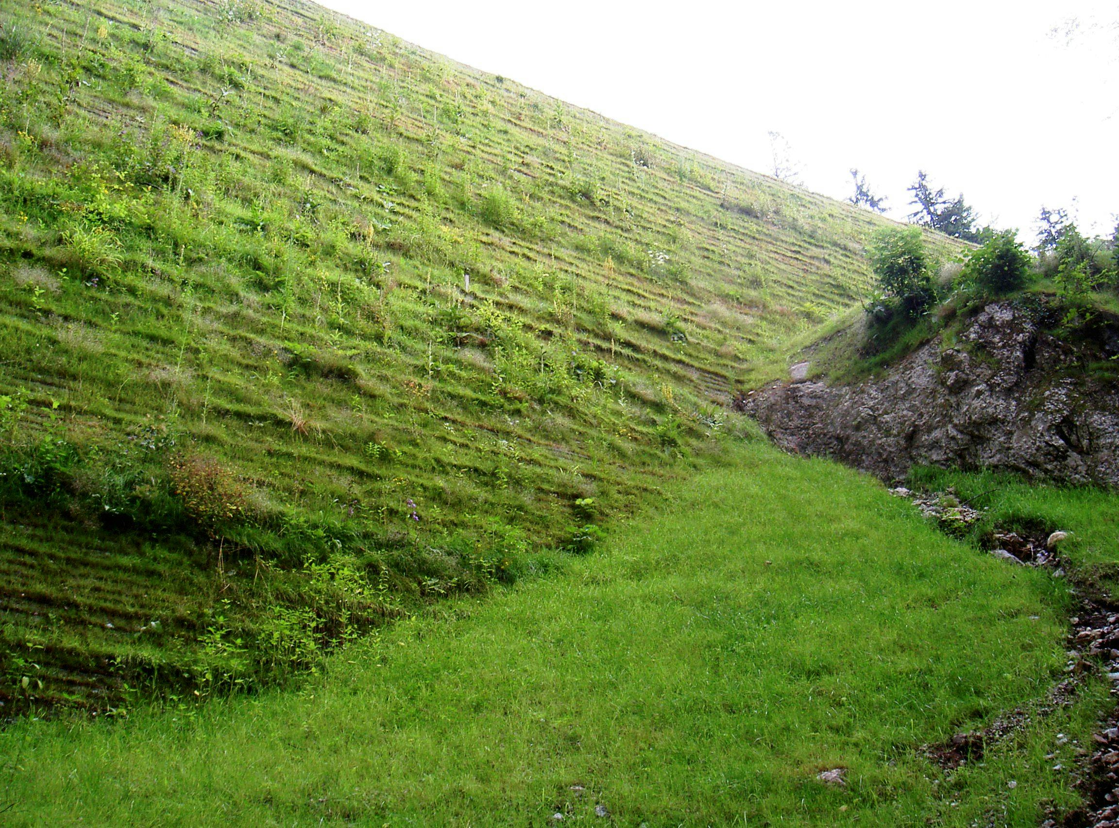
Experience in the region had shown that to provide a permanent vegetated slope face, which did not require irrigation, limited the slope face angle to a maximum of 2V:1H (2 vertical units to 1 horizontal unit). This maximum slope face angle, together with the realignment of the highway, made the requirement for the slope to be 34 m (111.5 ft) in height. Furthermore, the steep incline of the existing hillside limited the embedment lengths of the reinforcement layers because of the existence of a rock stratum at or near ground surface.
A design analysis of the steep reinforced slope was performed using a limit equilibrium approach, taking due account of National design standards.
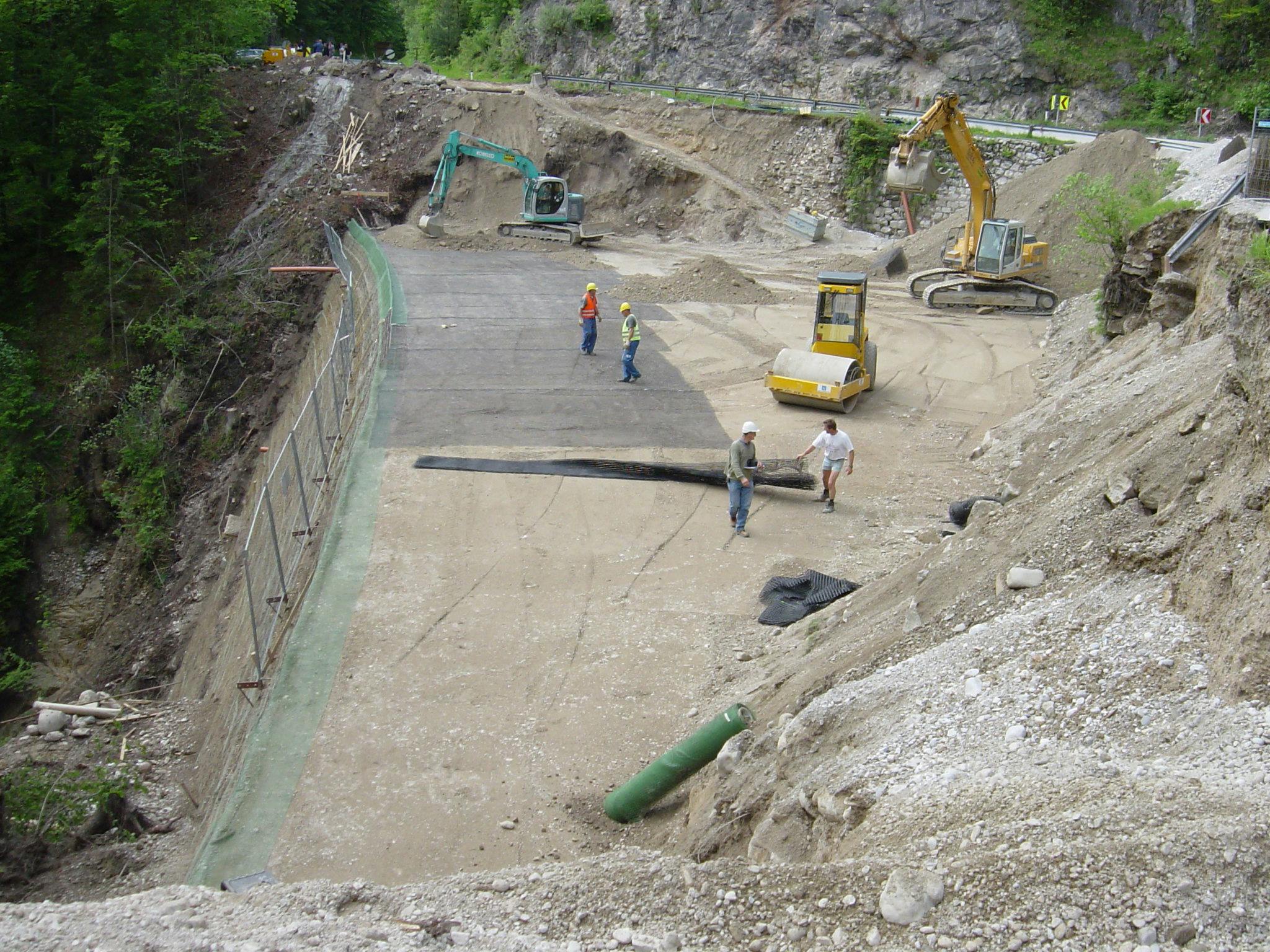
Because of the limited base width available, good quality granular material had to be used throughout as the reinforced fill, and this was compacted to good density specifications.
Depending on the location within the steep reinforced slope, layers of MIRAGRID® GX200/30 and MIRAGRID GX110/30 geogrid reinforcement, having ultimate tensile strengths of 200 kN/m (44,960 lbf/ft) and 110 kN/m (24,729 lbf/ft) respectively, were used. These geogrids are made of high-strength polyester yarns encased within a robust PVC coating and have excellent strength, extension, and durability properties.
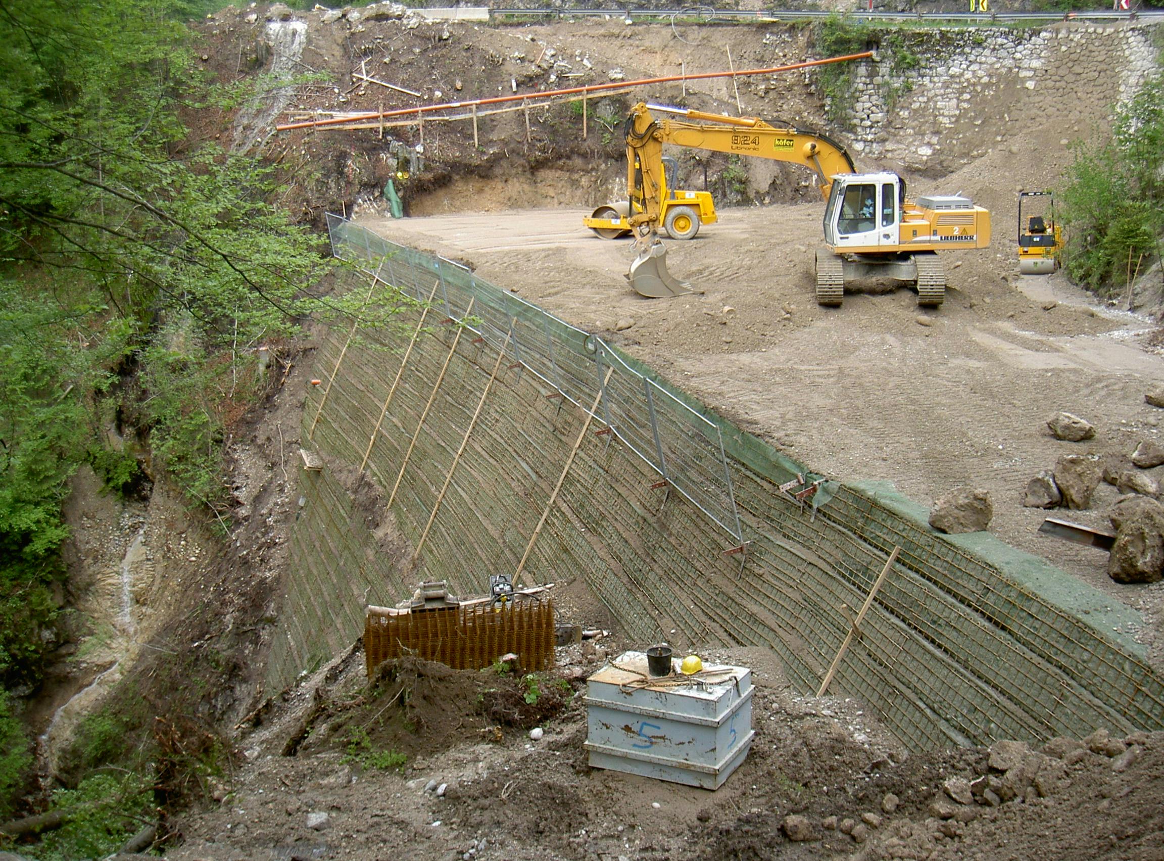
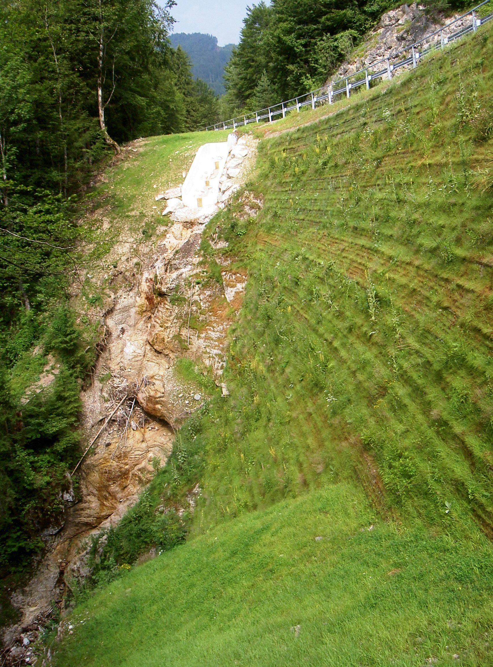
At the toe of the steep slope, it was not possible to provide a graded earth foundation base, so a concrete foundation block was constructed into the rock stratum. This ensured a stable toe foundation for the slope.
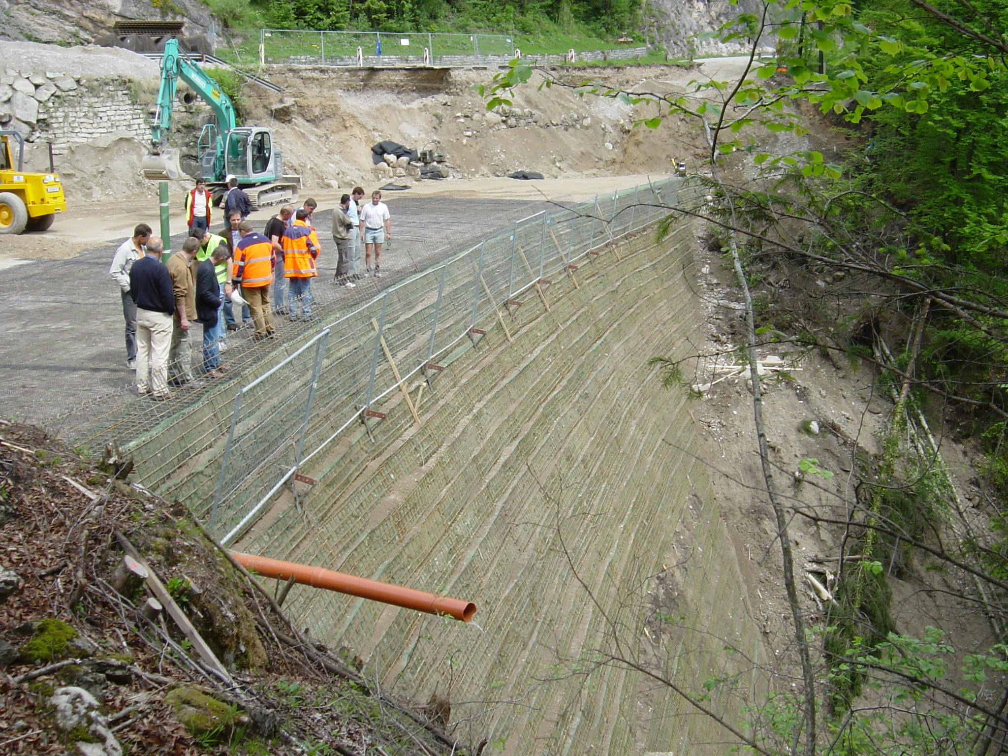
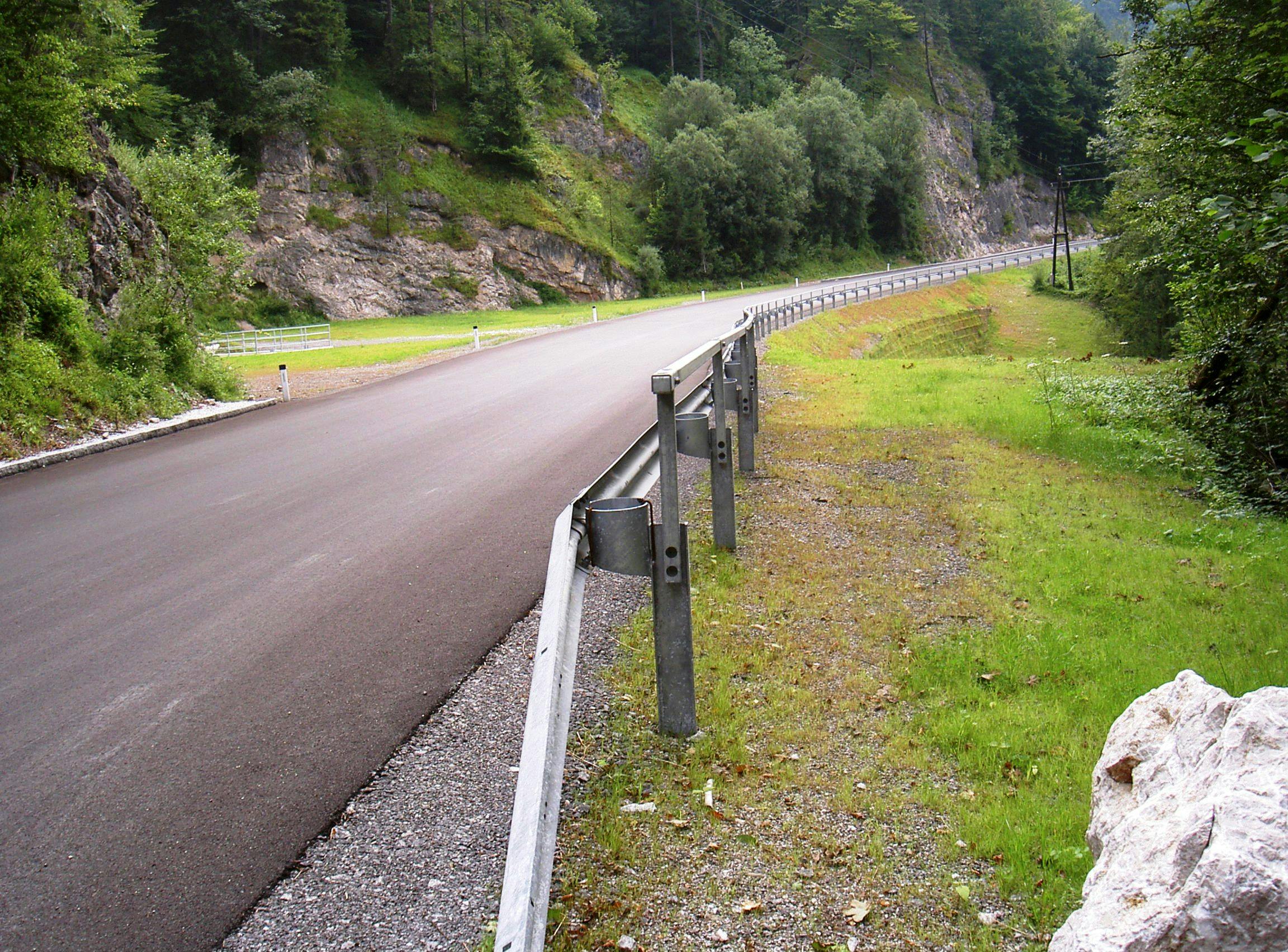
A value solution was found by using a geosynthetic reinforced steep slope to realign the highway, making it more stable and improving traffic safety. Several important aspects had to be accounted for at the design stage. These included the provision of a natural-looking slope face to blend in with the surrounding environment, the steep slope had to be constructed in layers of reinforcement, making construction difficult, and the cost had to remain within the authority's budget.
To form a smooth surface at the slope face, a steel mesh facing system was used. The steel mesh was bent to the required 2V:1H (2 vertical units to 1 horizontal unit) face angle and consisted of units 0.5 m (1.64 ft) high, which coincided with the vertical spacings between the geogrid reinforcement layers.
This steel mesh facing was relatively flexible, which enabled settlement of the fill during slope construction without creating undue deformations of the slope face. Inside the steel mesh facing, an erosion protection grid made of glass fibers was installed. The role of this glass grid is to protect the soil face from surface erosion until surface vegetation growth has been established. The glass grid also provides long-term local stability to the slope face.
Immediately behind the steel mesh and glass grid facing, good-quality topsoil was placed to enable good vegetation growth, followed by the placement and compaction of the granular reinforced fill. It had been observed that substantial quantities of groundwater seeping out of the hillside had contributed to the failure of the existing stone masonry wall. Consequently, extensive drainage measures were installed in the new slope to manage this groundwater seepage in a controlled manner. In the lower part of the slope, a geocomposite drainage layer was installed at the rock face. In the upper part of the slope, gravel drainage materials were used to intercept groundwater flows. The seepage water was then channeled by drainage pipes through the reinforced fill and out through the face of the reinforced slope, where it was discharged into the adjacent River Enns.
The value of this reinforced slope solution has proven to be very good, with its cost being around 50% of the cost of the originally proposed bridge solution.

RODLAUER BRIDGE, STYRIA, AUSTRIA
RODLAUER BRIDGE, STYRIA, AUSTRIA
RODLAUER BRIDGE, STYRIA, AUSTRIA
RODLAUER BRIDGE, STYRIA, AUSTRIA
RODLAUER BRIDGE, STYRIA, AUSTRIA
RODLAUER BRIDGE, STYRIA, AUSTRIA
RODLAUER BRIDGE, STYRIA, AUSTRIA
RODLAUER BRIDGE, STYRIA, AUSTRIA
RODLAUER BRIDGE, STYRIA, AUSTRIA
RODLAUER BRIDGE, STYRIA, AUSTRIA
RODLAUER BRIDGE, STYRIA, AUSTRIA
RODLAUER BRIDGE, STYRIA, AUSTRIA
RODLAUER BRIDGE, STYRIA, AUSTRIA
Flood protection for Reinland Drain in Manitoba
PROPEX® Armormax® stabilized the eroded Reinland Drain, reducing costs and emissions while ensuring long-term flood protection with reinforced vegetation growth.

Comprehensive containment and capping at Thailand’s ESBEC landfill
Solmax supplied GSE® HD liners and BENTOLINER® GCLs to line and cap Thailand’s ESBEC landfill, ensuring full containment, leachate and gas control, and compliance with national and international waste standards.

Providing a stabilized platform for site development in soft soil and flood-prone areas: an alternative to traditional stabilization methods
MIRAFI® RS580i stabilized parking areas at Knapheide’s Moncks Corner facility over soft, floodplain-adjacent soils, enabling rapid construction, eliminating chemical treatment, reducing material haulage, and delivering durable performance under heavy vehicle loading.