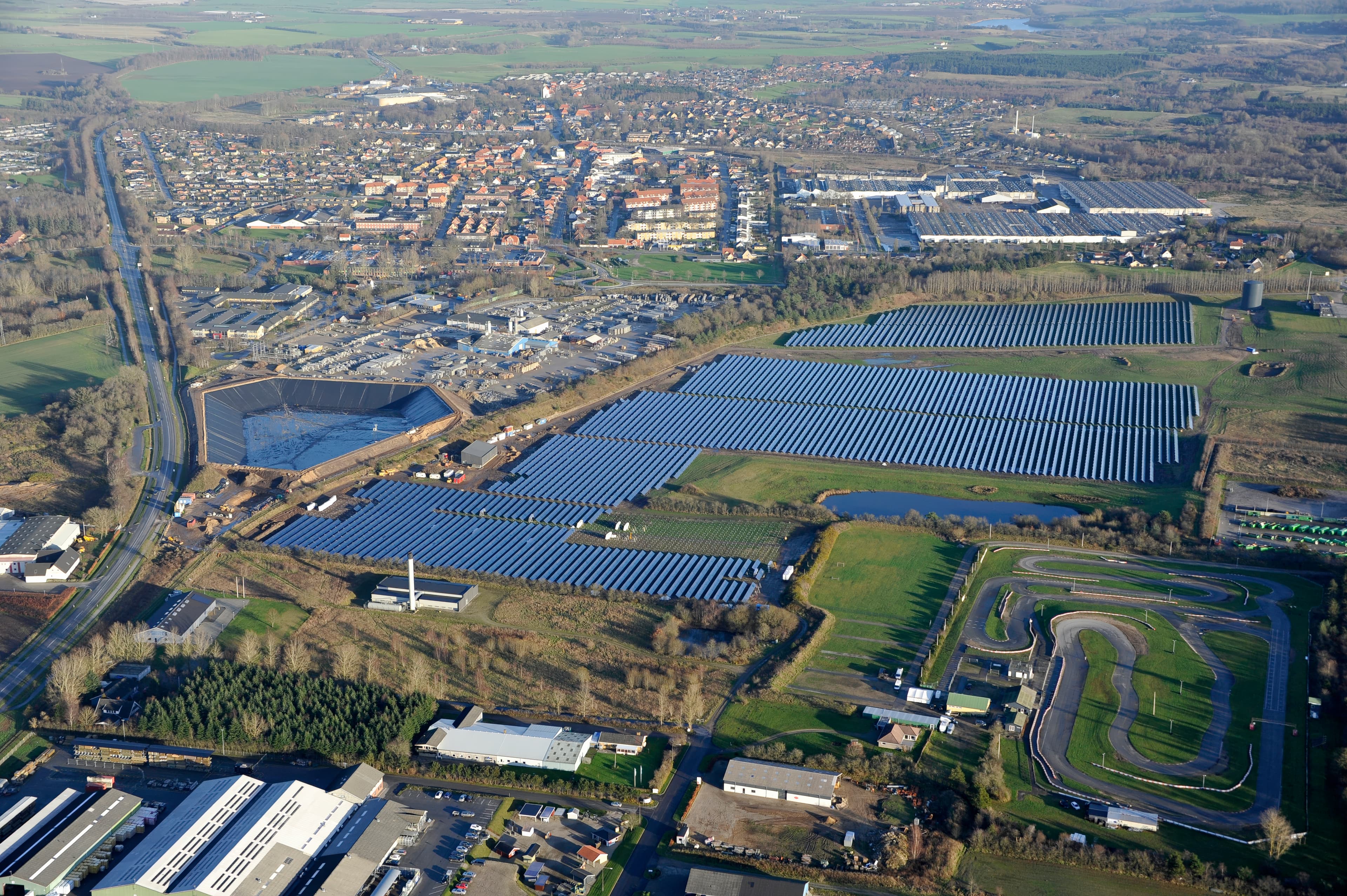
World’s largest pit thermal storage in Vojens
In Vojens, Denmark, a 200,000 m³ pit thermal storage basin stores surplus solar heat from a 70,000 m² collector field. Using Solmax geosynthetics, the system reduces CO₂ emissions by 6,000 tons annually.
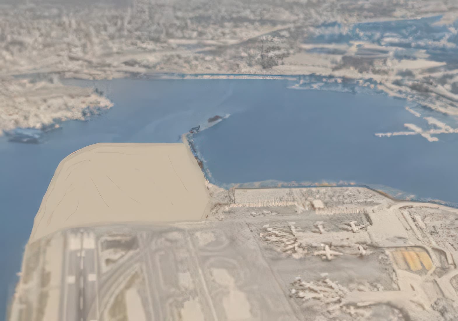
A runway overrun area had to be constructed at the east end of runway 13-31 at New York’s La Guardia International Airport. This was due to several overrun incidents occurring that brought political and safety impetus to the construction of this overrun area. This impetus also dictated that the overrun area be completed in a short period of time. The project entailed the construction of a 150 m long by 230 m wide overrun area, which would be predominantly covered with grass, but would also have a jet blast pavement area as well as an emergency access roadway. The overrun area is constructed in a broad inter-tidal mud flat consisting of a 23 m thick layer of soft, normally consolidated organic clay. The undrained shear strength of this organic clay varies between 5 and 10 kPa at ground surface and increases linearly with depth at a rate of 1.5 kPa/m. Below this organic clay layer are glacial deposits (dense sands and over consolidated clays and silts) of thickness around 35 m.
The challenge of this project was to place fill on the soft, normally consolidated organic clay without instability occurring. The historical approach to land reclamation at La Guardia had been end-dumping of fill, which had created extensive, uncontrolled mud waves. Mud wave creation was deemed unacceptable for this project due to the close proximity of a federal shipping channel and community concerns about increased “low-tide” odor. A number of design concepts were investigated for the overrun area. These included structural decking, pre-dredging and filling, or a geotextile reinforced construction.
The latter solution was adopted because it was the most cost-effective and least disruptive construction methodology. In order to accomplish the filling in the inter-tidal area without creating mud waves, the design prescribed detailed stage construction procedures. This staged design incorporated the installation of a layer of high-strength geotextile reinforcement across the surface of the soft organic clay prior to the placement of hydraulically pumped sand fill. The maximum tensile load and extension requirements for the geotextile reinforcement were calculated by evaluating the various geometric combinations and loadings. The geotextile reinforcement used was MIRAFI® PET200-150, which is a high-strength, high-modulus, woven polyester geotextile having an ultimate tensile strength of 200 kN/m in the length direction and 150 kN/m in the cross direction. The high cross-directional strength was required to ensure sewn seam strengths in this direction would meet the 60 kN/m design strength required.
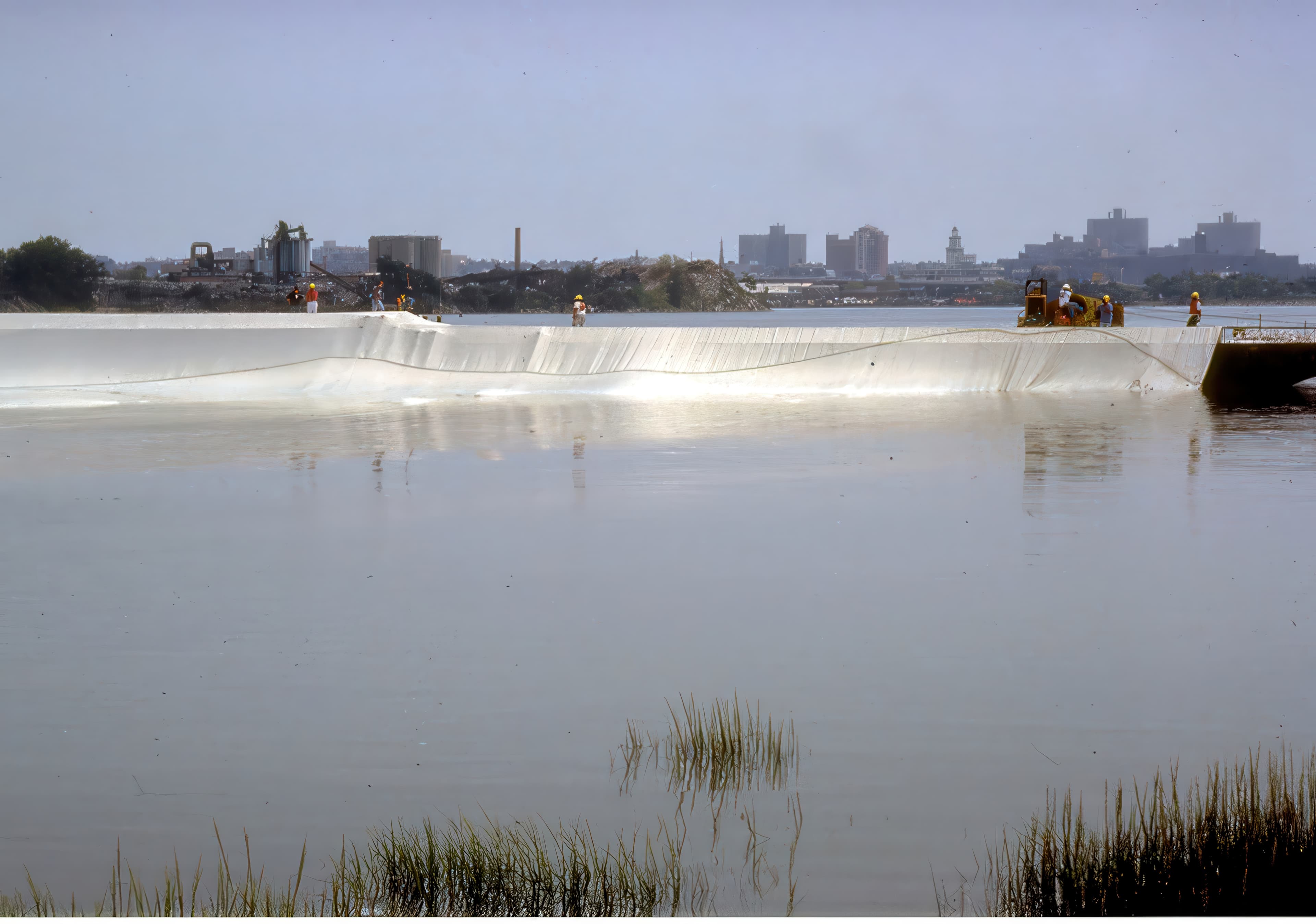
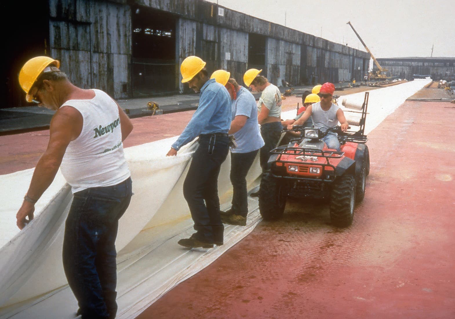
The contractor elected to use three barges, coupled in tandem, with a total length of 230 m for the geotextile reinforcement deployment. It was planned to cover the whole soft organic clay area using two large fabricated sheets of geotextile reinforcement, overlapped by 15 m at their joins. Lengths of MIRAFI PET200-150 geotextile reinforcement were rolled out along the deck of the barges and the joins seamed to produce the 60 kN/m seam strength requirement. The sewn geotextile was folded in an accordion-like fashion on the barge decks for easy deployment. During high tide, the barges were maneuvered close to the shoreline with the MIRAFI PET200-150 geotextile reinforcement unfurled off the barges and onto the shoreline. The geotextile was anchored in place and then the barges were slowly pulled from shore with the geotextile reinforcement unfurling into the water and progressively sinking onto the bay bottom, where it was secured with sandbags. The deployment of the two large fabricated sheets of MIRAFI PET200-150 geotextile reinforcement took place on two weekends when both runway closures and midday high tides coincided, with the unfurling process taking approximately 90 minutes per sheet.
The filling over the geotextile reinforcement was specified as hydraulically placed sand fill because this was the only placement method which could produce the low load levels and the flat slopes necessary for stability. The fill was placed in lifts no greater than 1 m, with the overall fill slope 1V:20H. With the interim overrun area in place, prefabricated vertical drains (PVDs) were installed through the sand fill into the soft organic clay foundation to increase the rate of consolidation. The PVDs were installed to an average depth of 25 m on a 1.2 m triangular grid, and installation was performed during runway closures late at night. The performance of the PVDs was good, with foundation consolidation rates approaching laboratory predictions. It was anticipated that at completion of construction, the final settlements would range from 3 m to 4.5 m at different locations in the filled area. There were no discernible mud waves created during the hydraulic filling, and subsoil displacements were minimal compared to the large displacements typical with the previous end-dumping methods.
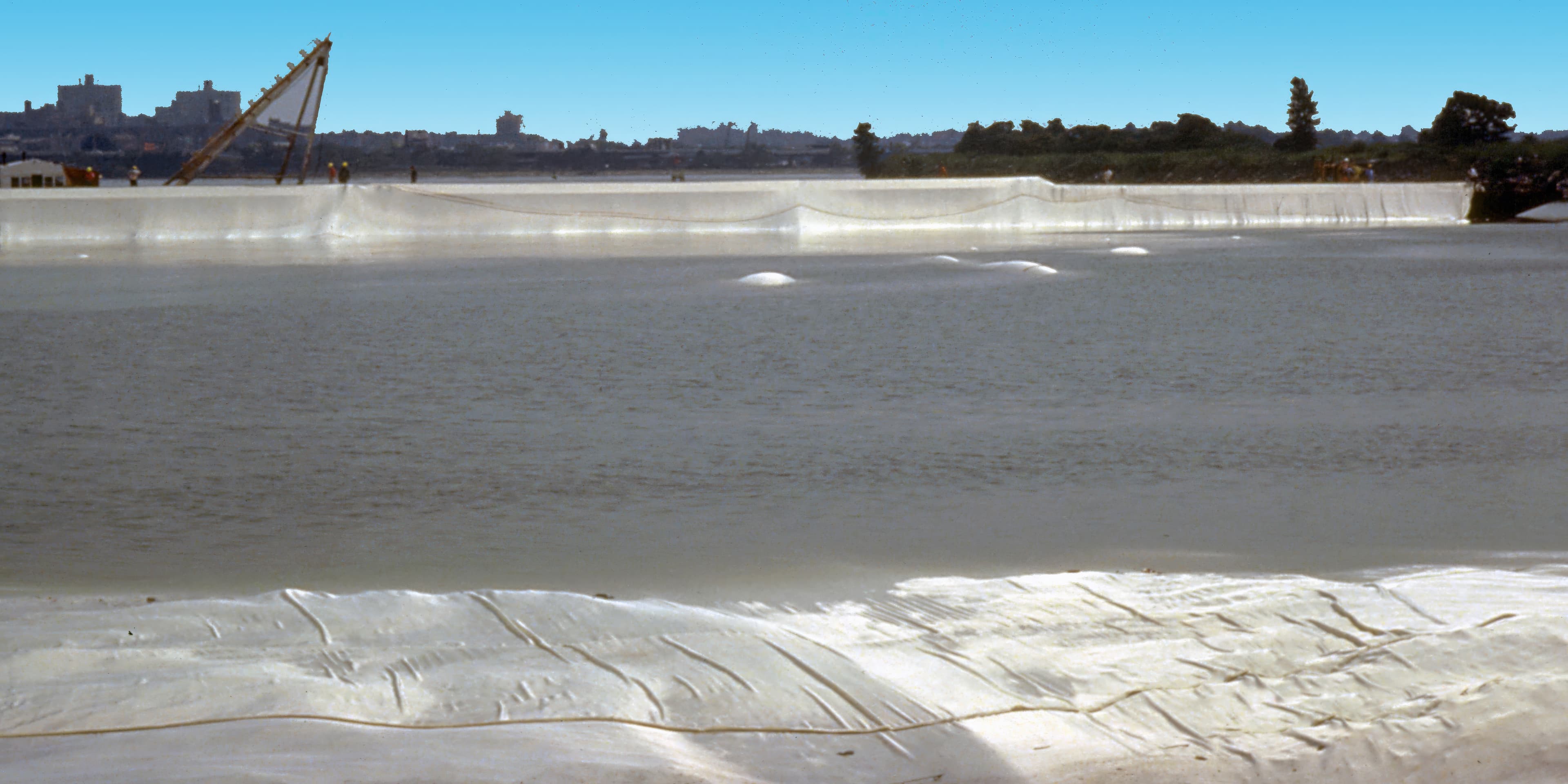
Runway overrun area, La Guardia
Hydraulically placed sand fill was added in lifts under 1 m, forming a shallow 1V:20H slope to maintain stability over the soft organic clay.
Prefabricated vertical drains were installed through the sand fill into the clay to about 25 m depth on a 1.2 m triangular grid to accelerate consolidation.
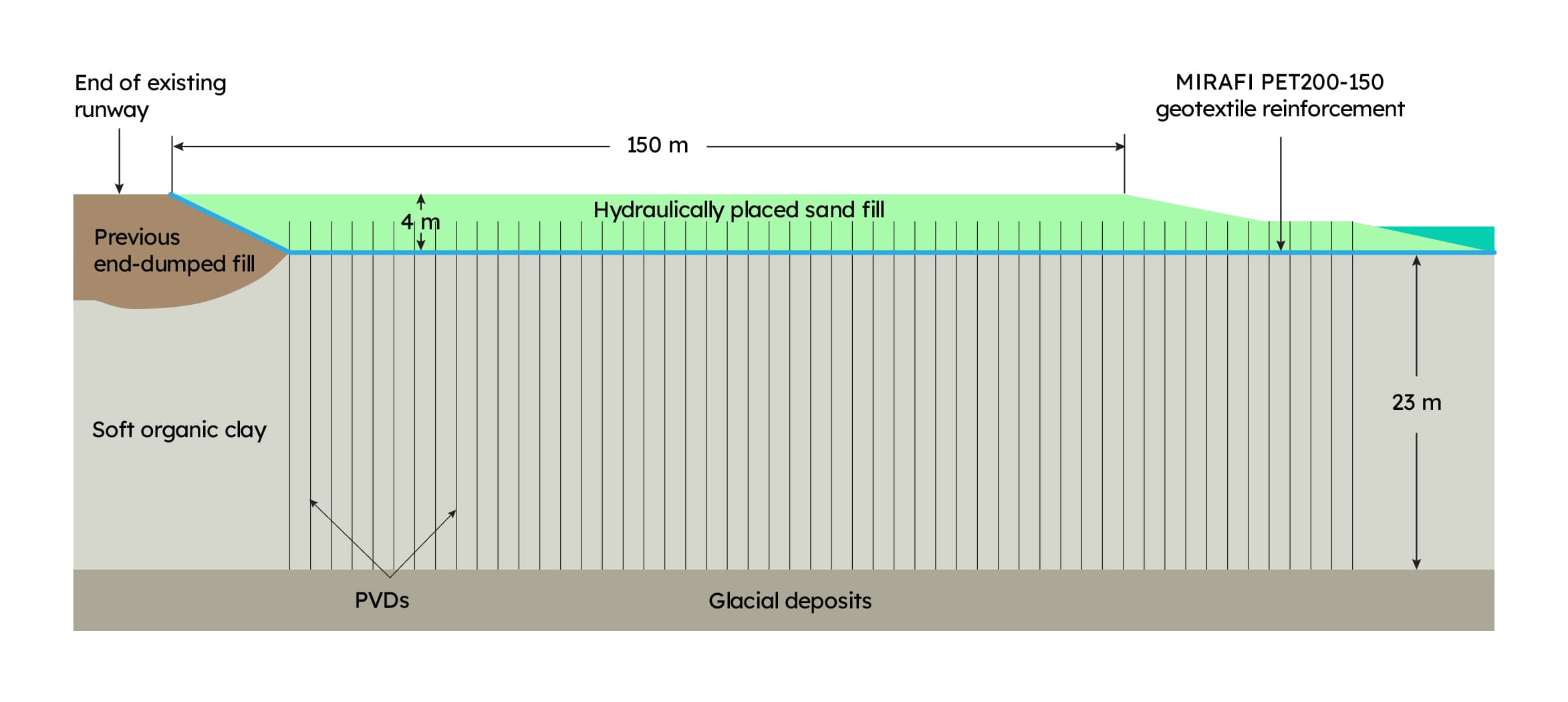
Typical cross section through the runway overrun area
World’s largest pit thermal storage in Vojens
In Vojens, Denmark, a 200,000 m³ pit thermal storage basin stores surplus solar heat from a 70,000 m² collector field. Using Solmax geosynthetics, the system reduces CO₂ emissions by 6,000 tons annually.
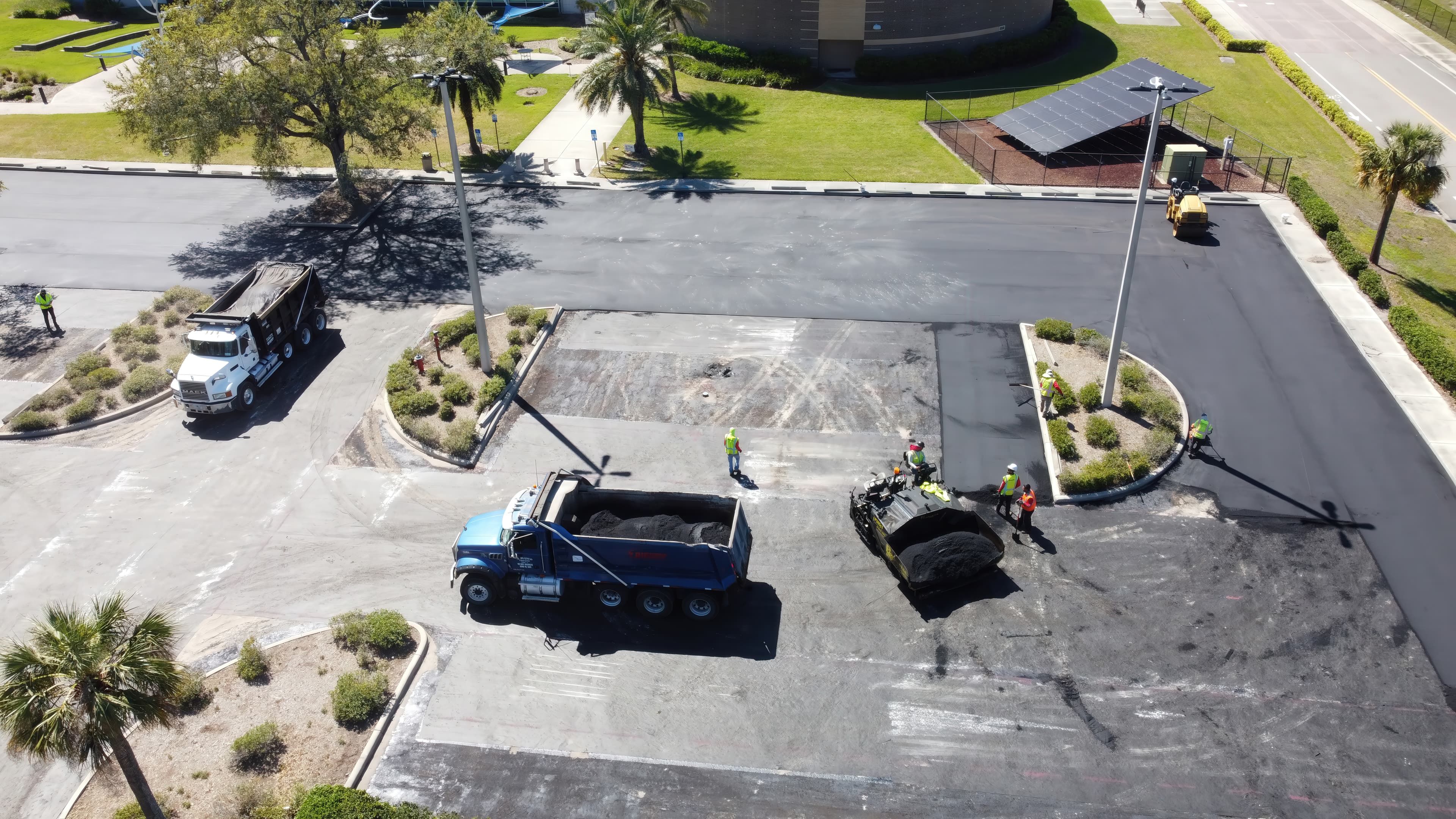
Extending parking lot overlay life at Hillsborough College – Brandon Campus
Hillsborough College – Brandon Campus used Petromat® MPV500 paving fabric to improve bonding, delay reflective cracking, and support longer-lasting pavement rehabilitation.
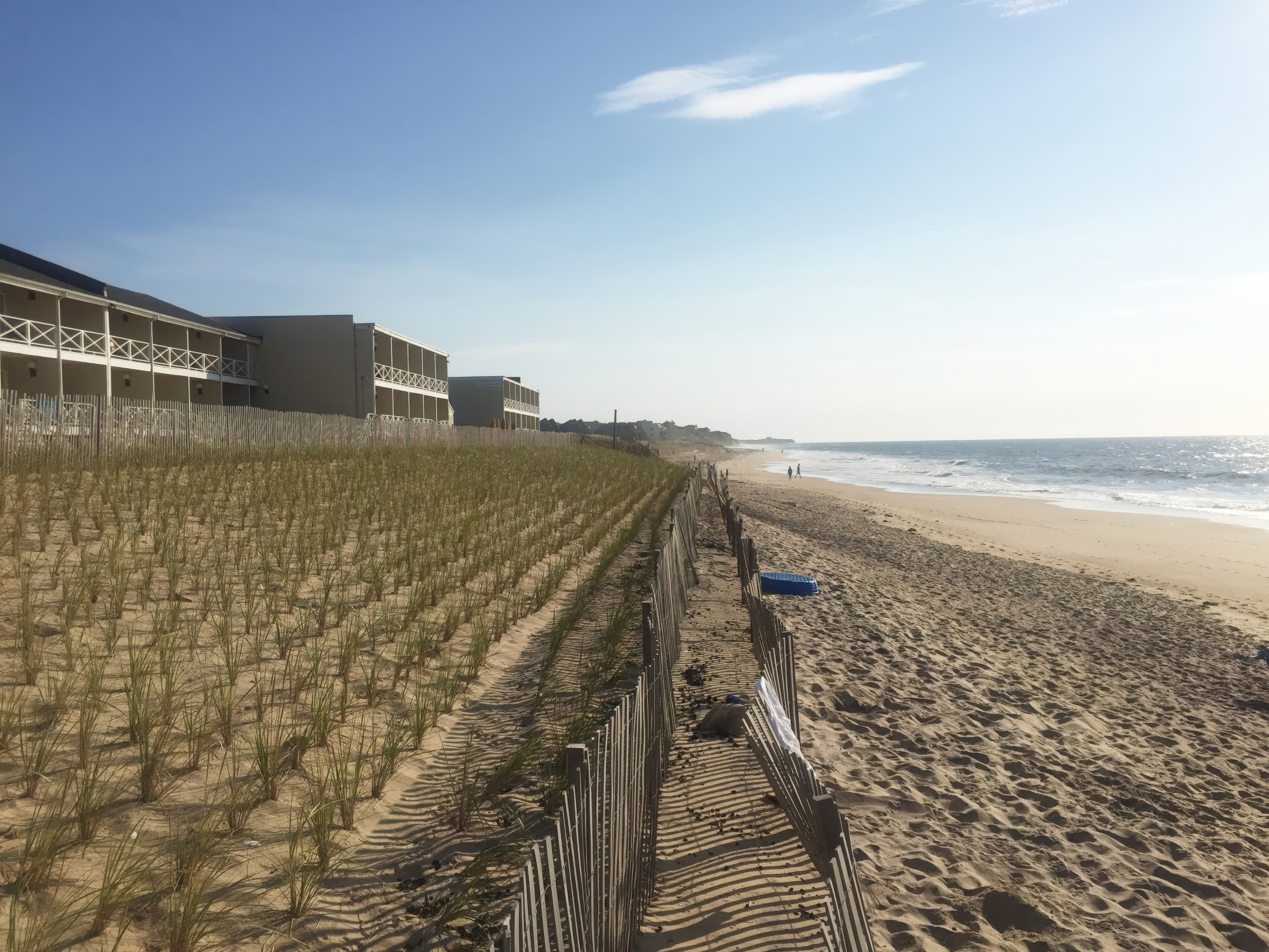
Reinforced dune construction for shoreline protection in Montauk
USACE stabilized the eroded Montauk shoreline using more than 11,000 GEOTUBE® Geobag sand containers and 3,200 ft of scour aprons to form a reinforced dune core, restoring storm protection for vulnerable commercial buildings.