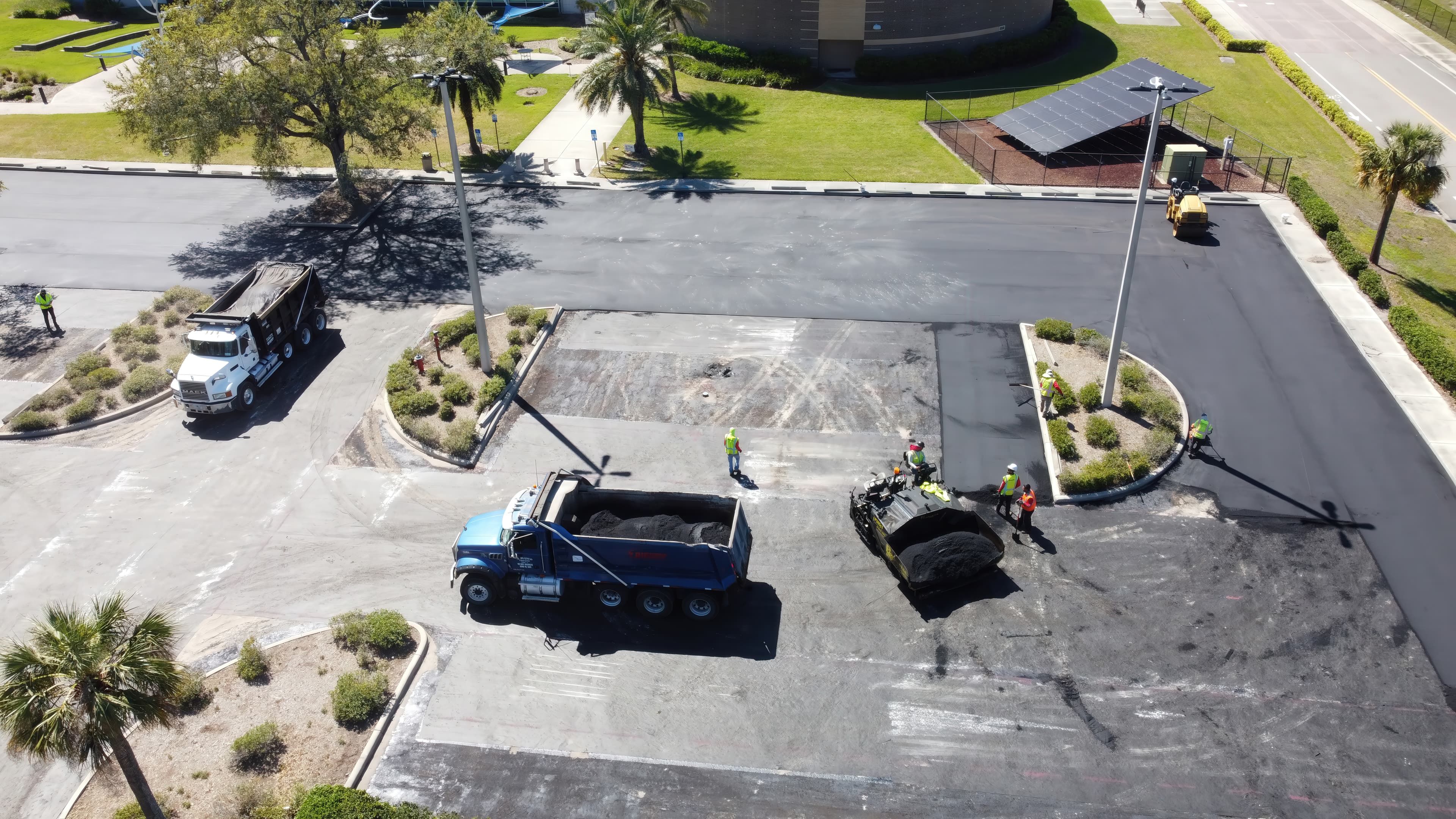
Extending parking lot overlay life at Hillsborough College – Brandon Campus
Hillsborough College – Brandon Campus used Petromat® MPV500 paving fabric to improve bonding, delay reflective cracking, and support longer-lasting pavement rehabilitation.
The Dinh Vu (Deep C) Industrial Zone (DVIZ) is located near the new Lach Huyen Deep Sea Port to the southeast of Haiphong City, the major port area for northern Vietnam. The various Deep C reclamations are being constructed to provide 3,000 ha of industrial development land, which is the largest industrial zone development in all of Vietnam. The Deep C II reclamation area has direct access to the new Lach Huyen Deep Sea Port via the newly completed Lach Huyen Bridge. The hydraulic conditions at the Deep C II reclamation site consist of mean low water level (LWL) at CD+1.5 m, with mean high water level (HWL) at CD+3.0 m. Normal water currents are low, ranging from 0.2 to 0.3 m/s. However, the area is subject to extreme storm events from typhoons where water levels can rise to CD+4.5 m. The seabed surface at the Deep C II reclamation site ranges from CD+1.5 m to CD+1 m; thus, it is at or just below LWL.
The upper 8 m of the seabed consists of very soft organic silty clay (marine clay) with the surface having an undrained shear strength of only 5 kPa. Below this is a 7 m thick layer of very soft clay with sand lenses. Below this are stiff clay layers, and finally, at around 35 m depth, a dense sandy gravel stratum. Because of the very low shear strength of the upper seabed layers, the stability of any land reclamation structures is limited. It was planned to sequentially construct several reclamation containment dykes extending out into the Deep C II reclamation area. This was done to enable part of the site to be reclaimed and developed while waiting for further demand and expansion.
The design of the reclamation dykes consisted of locally dredged silty sand fill contained between outer GEOTUBE® containment units. GEOTUBE units were chosen for the outer protection for the reclamation dykes for a number of reasons, namely:
GEOTUBE units have an efficient contact surface with soft foundation soils and do not suffer from local shear failures as rock fill does.
The sizing of the GEOTUBE units provided adequate mass gravity to resist water forces caused by extreme typhoon storms. The height of the GEOTUBE units surpassed that of the water height during typhoon storms.
The GEOTUBE units were designed with a long-term design life in exposed conditions, as it may be many years before any new expansion covers the existing exposed dykes. This allowed adequate time for reclamation expansion to cover the previously installed GEOTUBE units. For the final outer dyke, rock armor is placed over the seaward side of the reclamation dyke to create a final, permanent protection. When expanding the reclamation area, it is not necessary to remove the GEOTUBE units, as they can simply be covered with reclamation fill and piled through during later development, unlike rockfill, which would need to be removed during expansion.
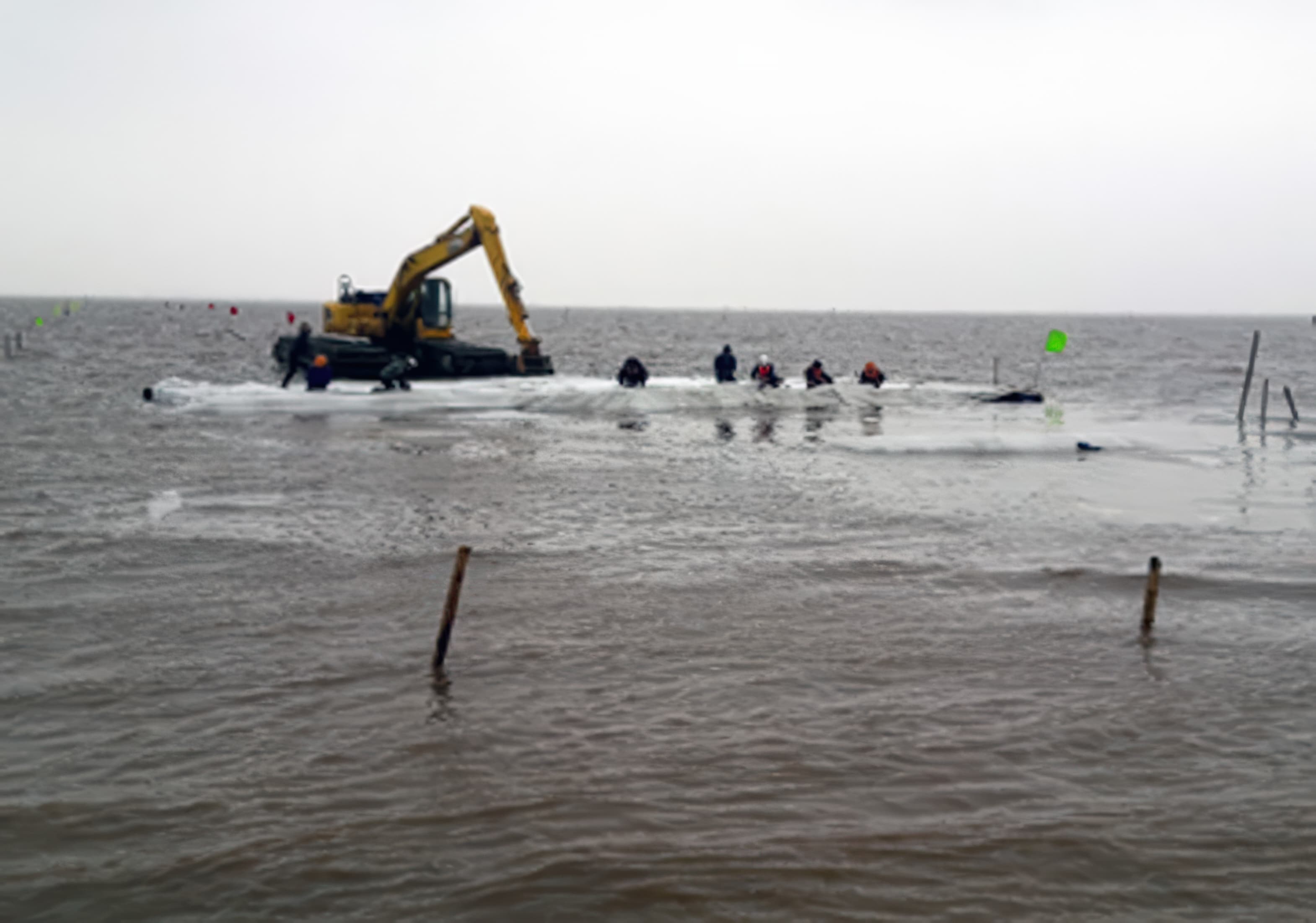
To provide the required stability for the reclamation dykes, a layer of MIRAFI® PET800 geotextile reinforcement, which has an initial characteristic tensile strength of 800 kN/m, was placed across the base of the reclamation dykes on the seabed. The strength and strain characteristics of this geotextile reinforcement met the stability requirements for the reclamation dykes determined at the design stage. The MIRAFI PET800 geotextile reinforcement was installed in 35 m × 15 m panels at low tide and anchored in place using bamboo stakes.
To provide some bending rigidity, bamboo mattresses were then installed beneath where the GEOTUBE containment units were to be located. Next, the bottom layer of GEOTUBE GT1000 containment units was laid out and filled with the locally dredged silty sand fill, with the area in between also filled with the silty sand. This procedure was repeated with the second layer of GEOTUBE units, with the silty sand fill continuing up to the completed reclamation dyke level.
Following this, an access pavement was constructed on top of the reclamation dyke to level CD+6.0 m. To prevent surface erosion of the dyke side slopes above the GEOTUBE units on the seaward side, a 0.3 m thick GEOTUBE sand filled mattress was used. To prevent toe instability on the seaward side of the dykes, a 0.5 m thick GEOTUBE mattress was placed.
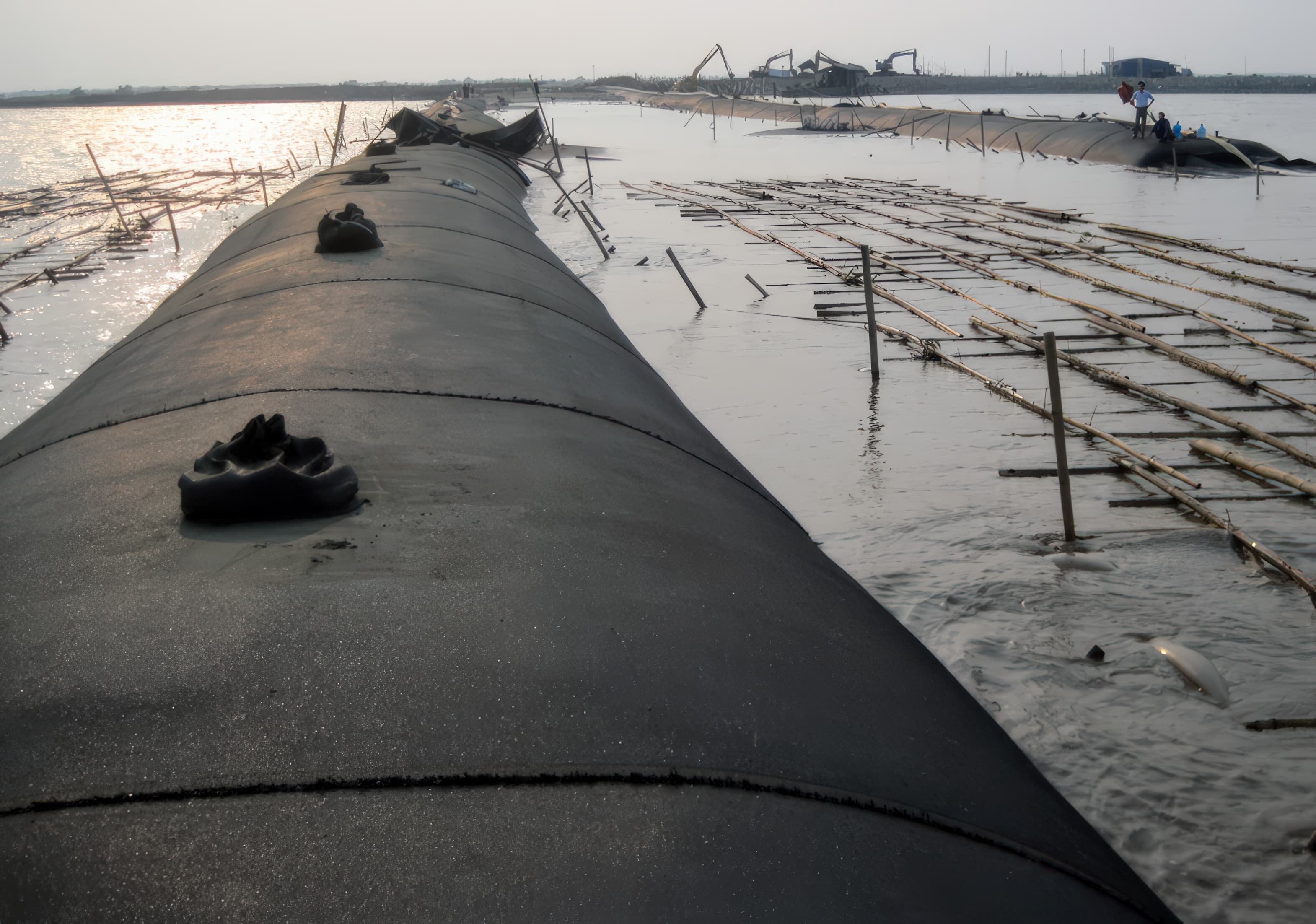
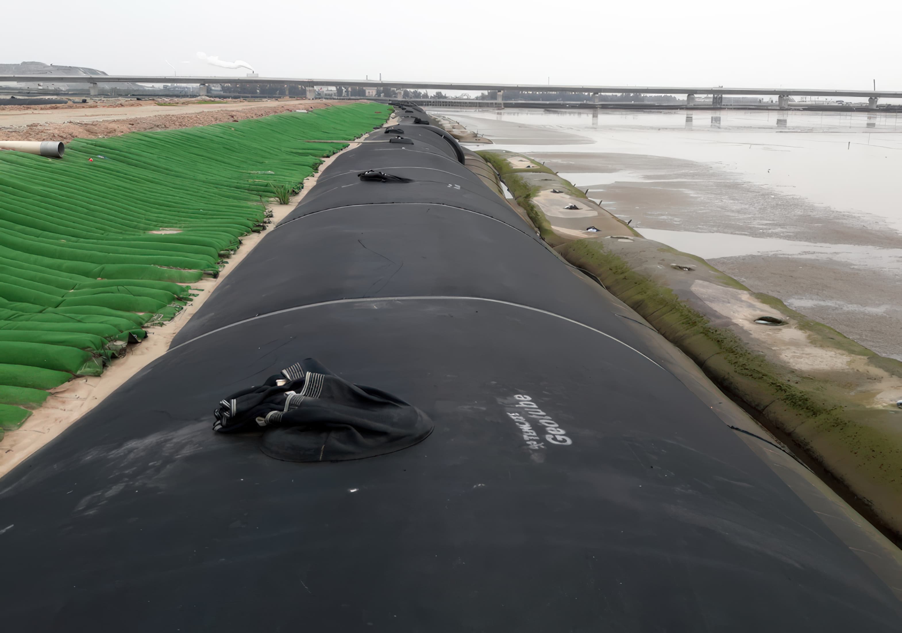
The GEOTUBE-protected reclamation dykes have continued to perform as required. A number of them have remained in an exposed condition for over four years with no discernible loss of serviceability.
Reclamation dykes were built with GEOTUBE containment units filled with locally dredged silty sand to provide stability on very soft seabed soils.
MIRAFI PET geotextile reinforcement was installed at the dyke base to meet stability requirements and support construction over weak marine clay.
Bamboo mattresses and layered GEOTUBE units formed the dyke structure, with protective GEOTUBE mattresses added to prevent erosion and toe instability.
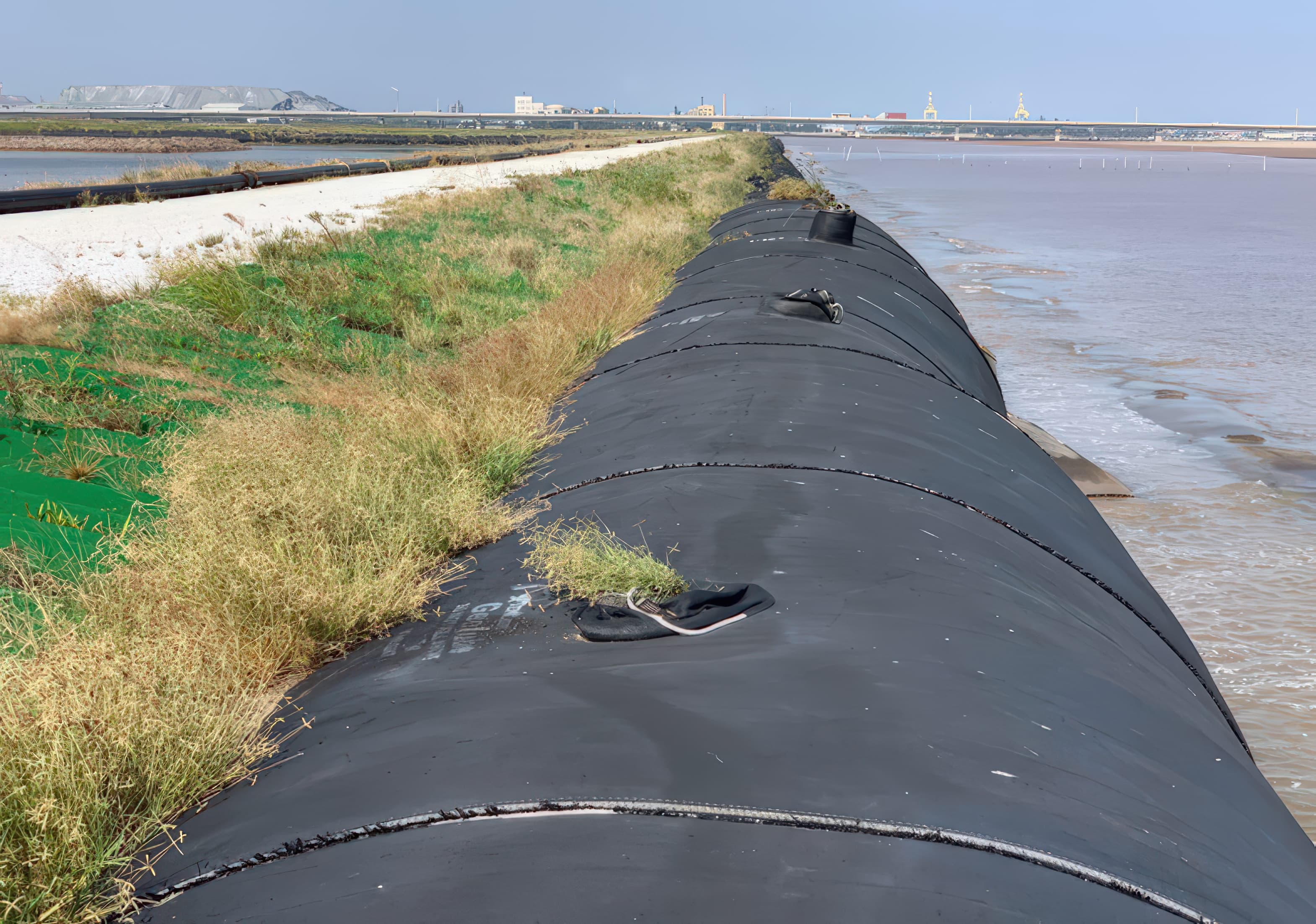
Reclamation dyke 4 years after construction
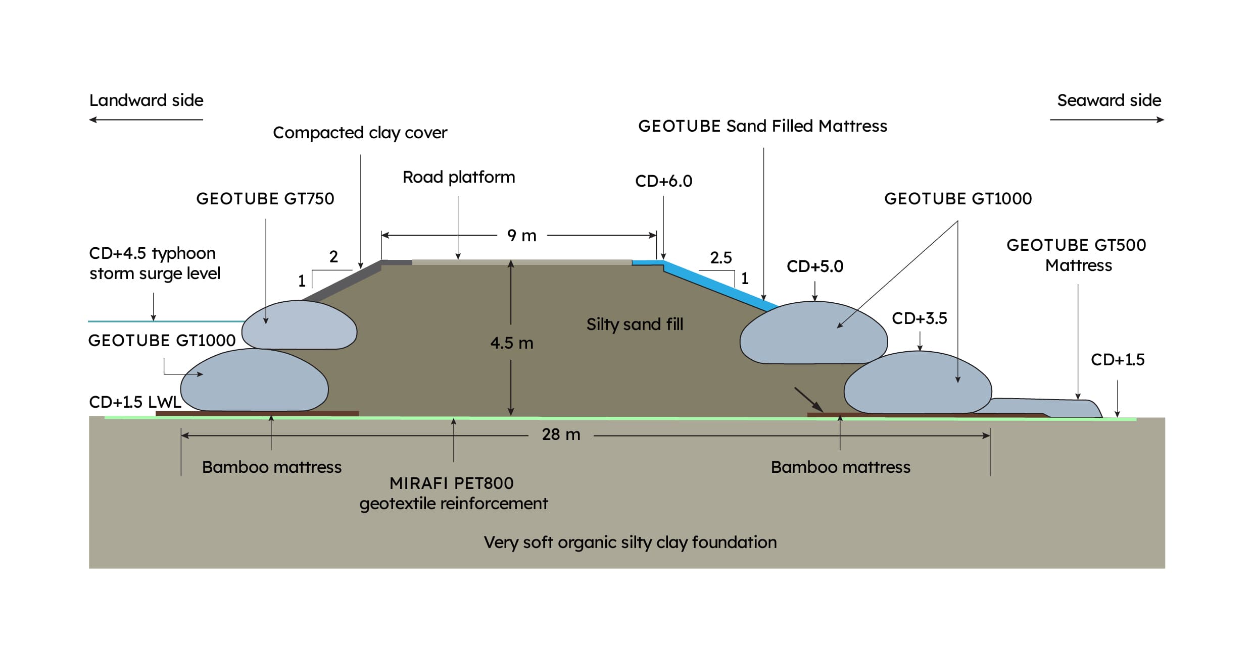
Cross section through containment dykes at Deep C II reclamation
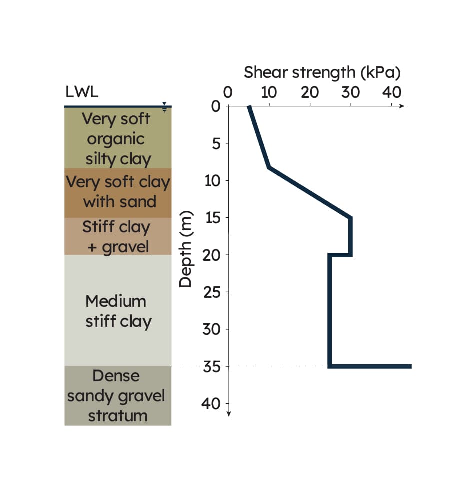
Foundation conditions at site
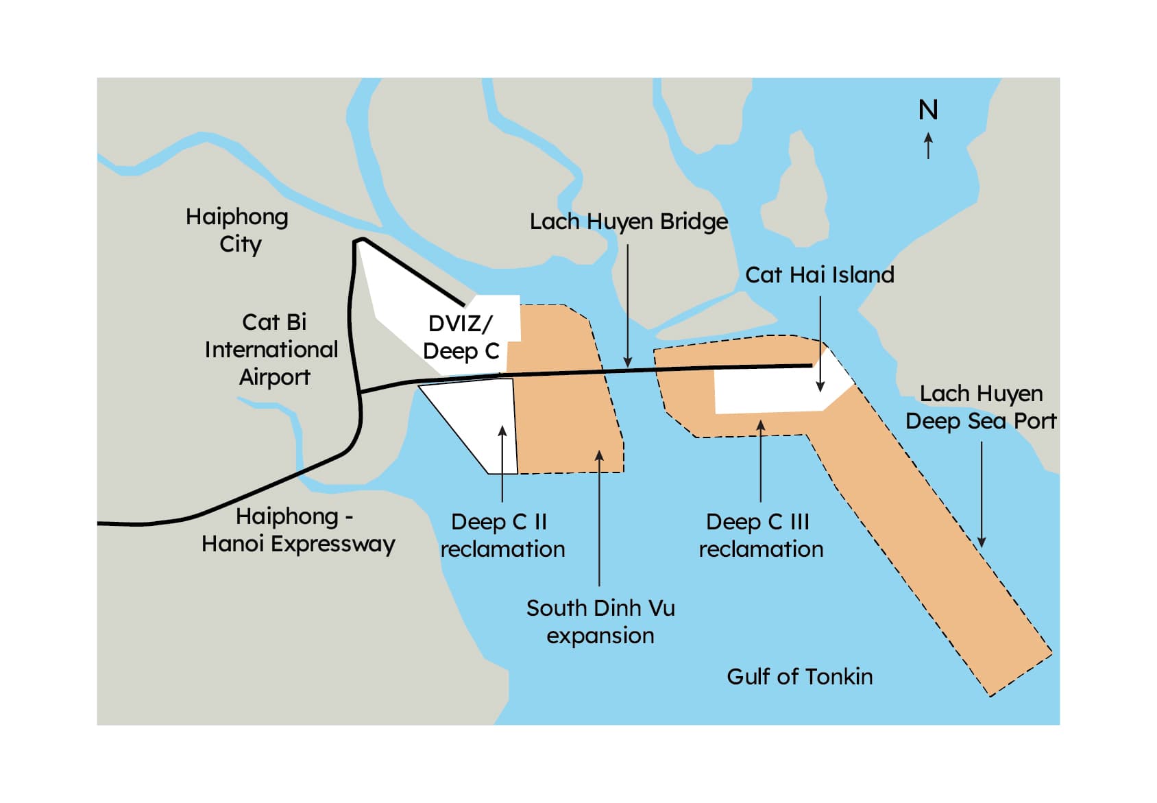
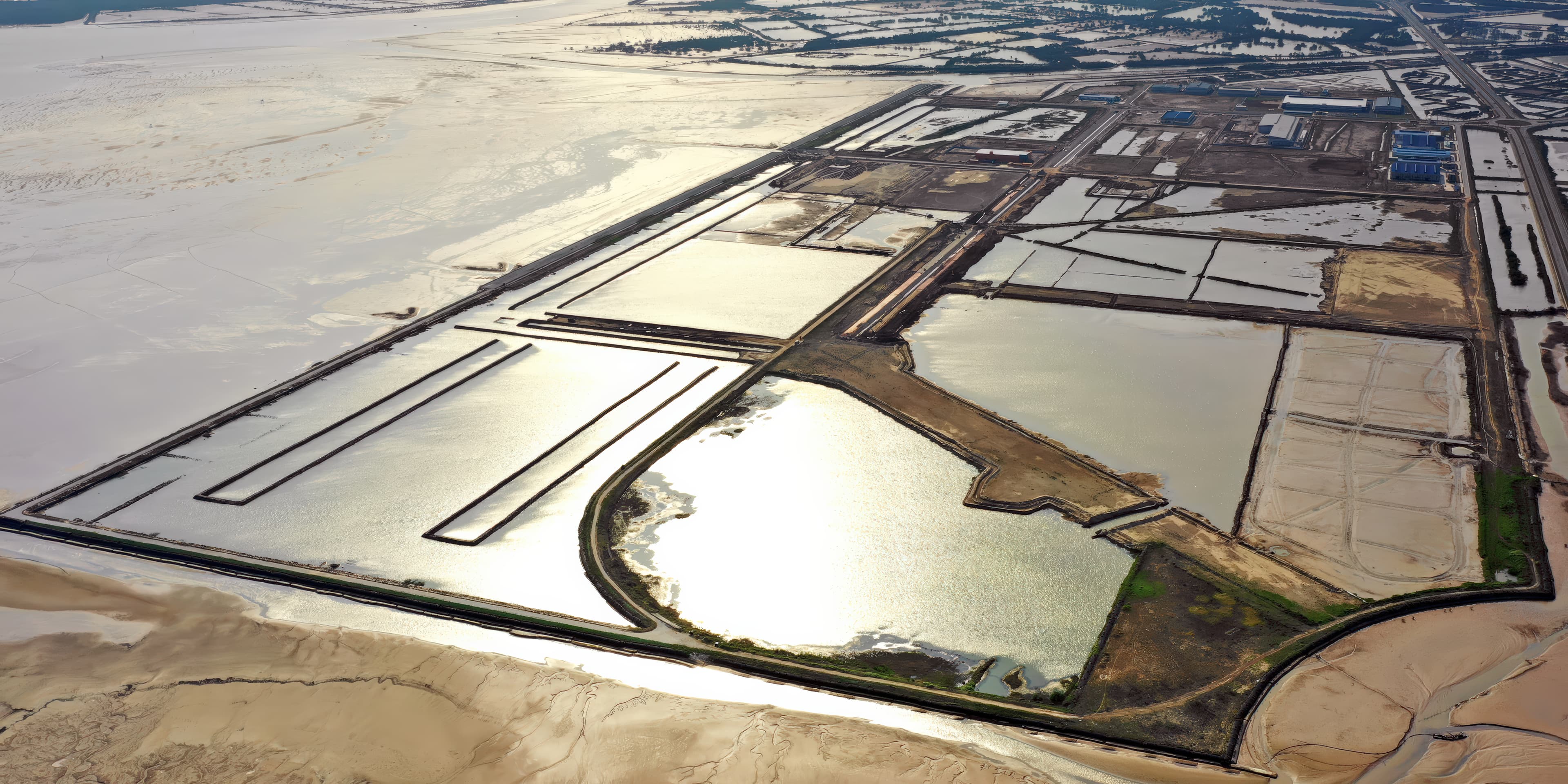
Location of Deep C II reclamation project
Extending parking lot overlay life at Hillsborough College – Brandon Campus
Hillsborough College – Brandon Campus used Petromat® MPV500 paving fabric to improve bonding, delay reflective cracking, and support longer-lasting pavement rehabilitation.
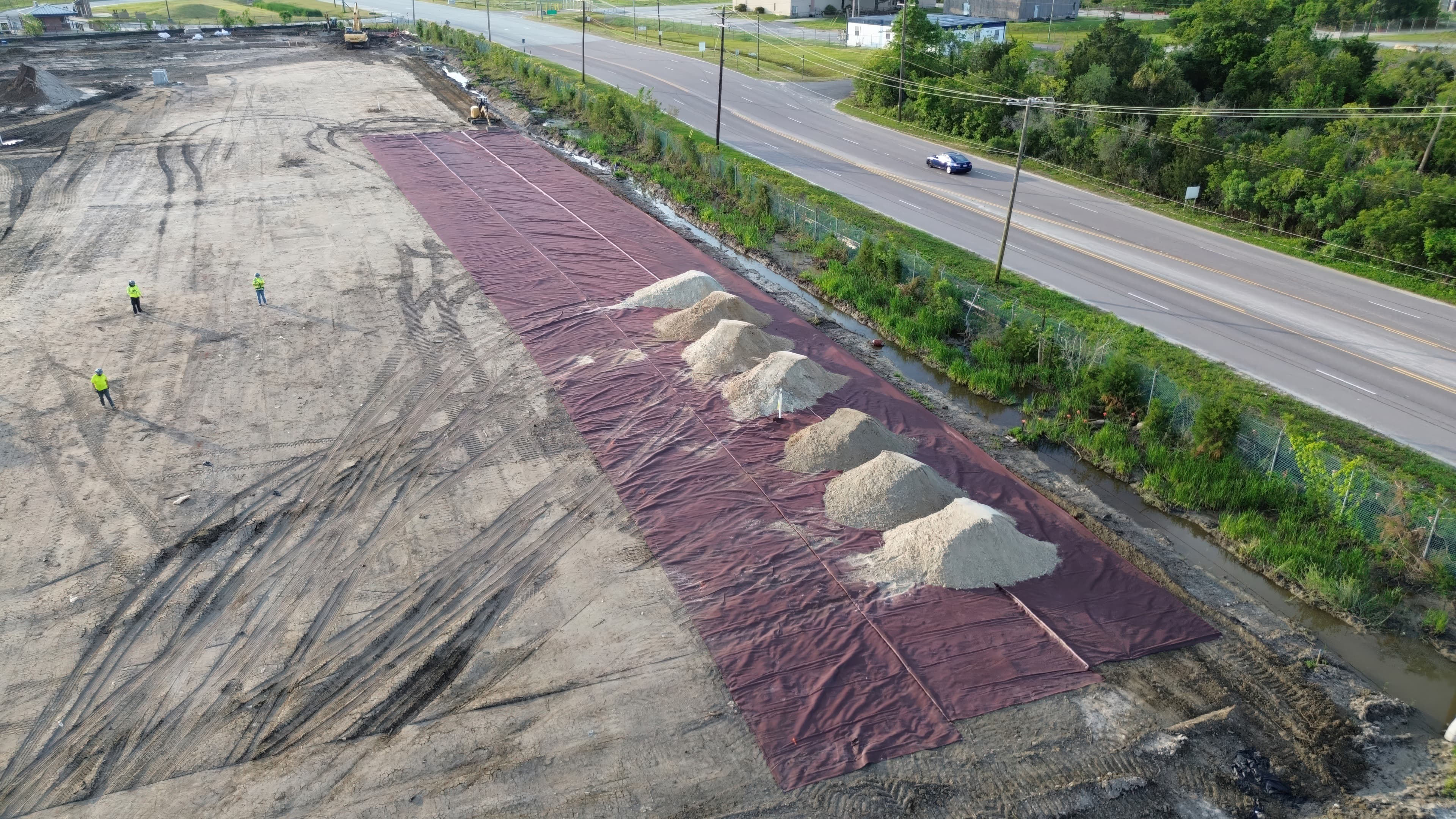
Managing differential settlement on soft landfill soils with MIRAFI
MIRAFI® RS380i stabilized pavements at FLETC Charleston over soft marine clays and landfill soils, reducing settlement risk while improving constructability and lowering costs.
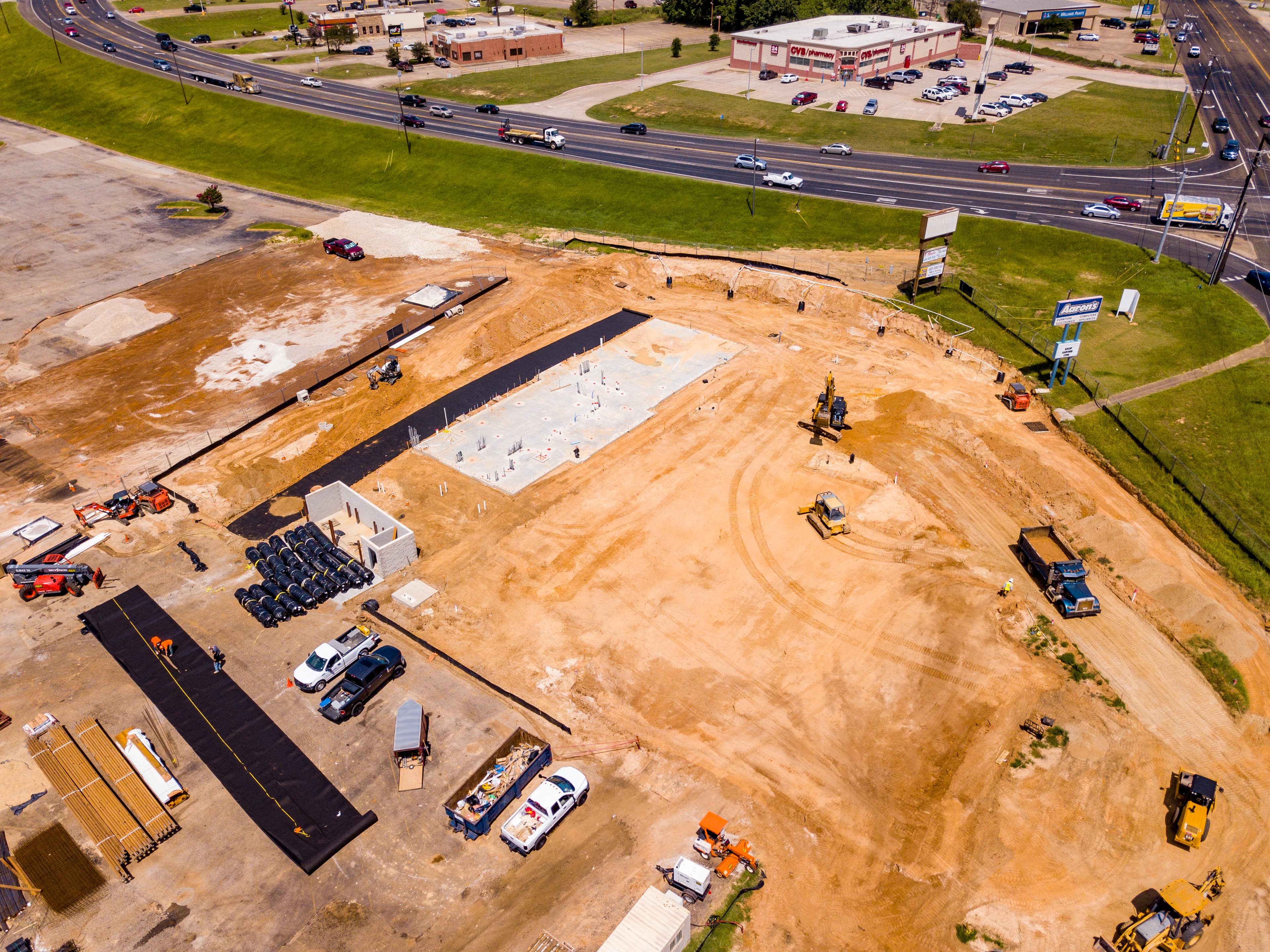
Texas retailer chooses modern engineering solutions
A Texas fast-food build used FABRINET® TP instead of aggregate for subsurface drainage. The solution reduced excavation, cut costs by 54 percent, sped up installation, and minimized environmental disruption.