>
Products
Technical note
9 Min read
FABRINET Coaldrain geocomposite
Drainage geocomposites consist of a geotextile filter and a polymeric core – with the two components bonded together by a heat lamination process. A geocomposite must satisfy design considerations, including filter and flow requirements based on site-specific conditions. Other factors affecting the selection of a drainage geocomposite include its interface shear strength, compression strength, and durability.
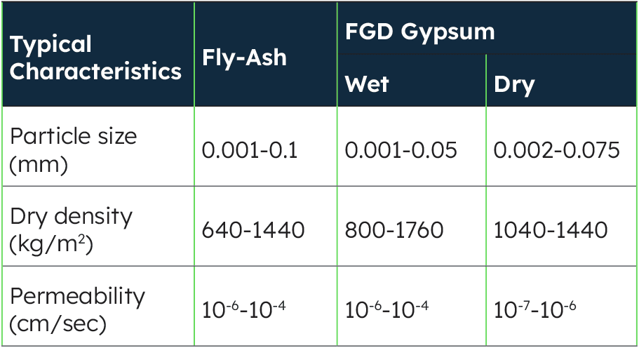
For some projects, such as a landfill cover, the emphasis may be on the thickness of the drainage core, so that seepage water will drain quickly without developing pore pressures. For other kinds of projects, such as a landfill base drainage layer, the compression strength of the core may be the overriding concern. For drainage geocomposites that are used in direct contact with fine CCRs, the filter design plays the most important role. This is understandable, as can be seen in Table 1, which presents a range of particle sizes for the fine CCRs fly ash and FGD gypsum. Because these CCRS are silt and clay-like in nature, it is difficult to design a filter that will effectively filter them, since most products and design methods are developed based on sand-sized particles. As a result, the opening size of most geotextiles is in the range of 0.1 to 0.3 mm, which is the size of sand particles. Filters against fly ash and FGD gypsum require geotextiles whose opening size is in the same range as their particle sizes.
FABRINET® Coaldrain geocomposite
The containment of CCRs in landfills and surface impoundments requires the use of a composite liner system, as illustrated in Figure 1. This kind of liner system typically consists of a drainage layer underlain by a geomembrane, which is itself underlain by a geosynthetic or a compacted clay liner. The drainage layer can be composed of sand, gravel or a drainage geocomposite. For the latter option, a geotextile must be selected such that it will ensure that there is no loss of fines from the base material into the drainage core. This selection process is based on empirical procedures, several of which have been published in the literature. Most of these published methods, however, are not applicable to very fine-graded materials, since they were developed using sand, which is easy to work with in experiments.
Most of these published methods, however, are not applicable to very fine-graded materials, since they were developed using sand, which is easy to work with in experiments. That said, the following relationship has proven to be reliable for fine-grained materials, such as silt:
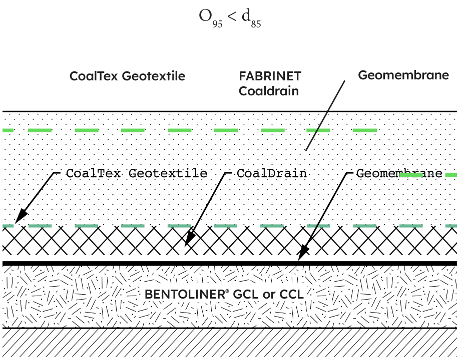
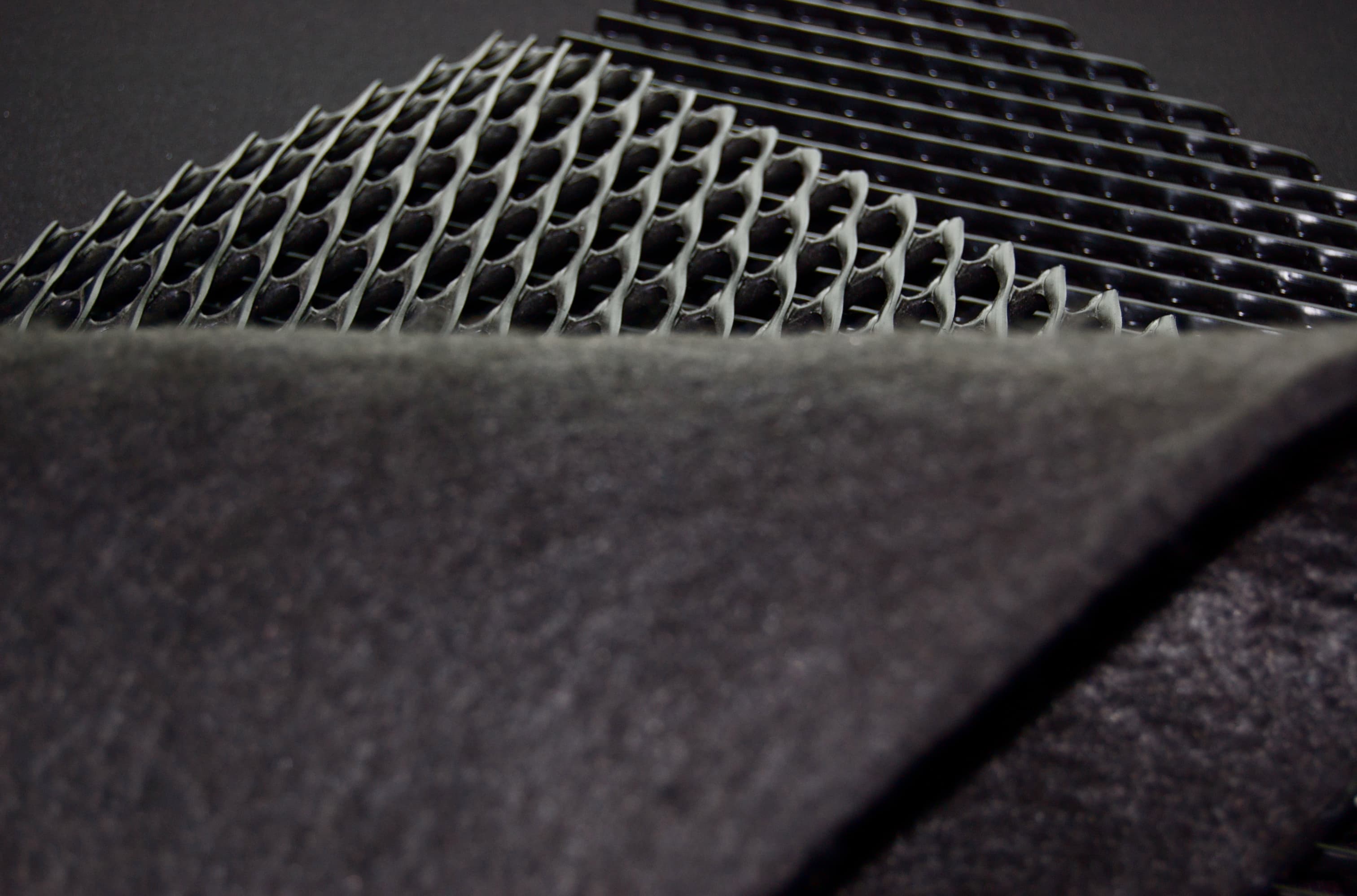
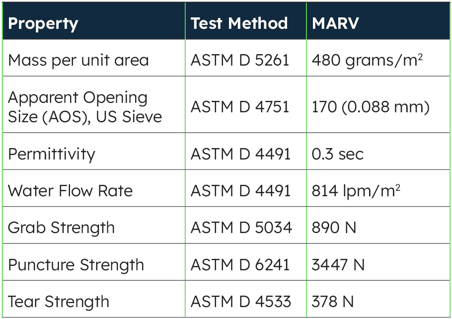
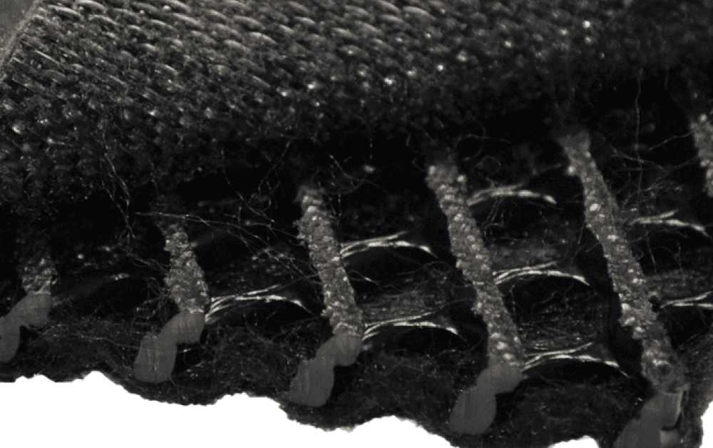
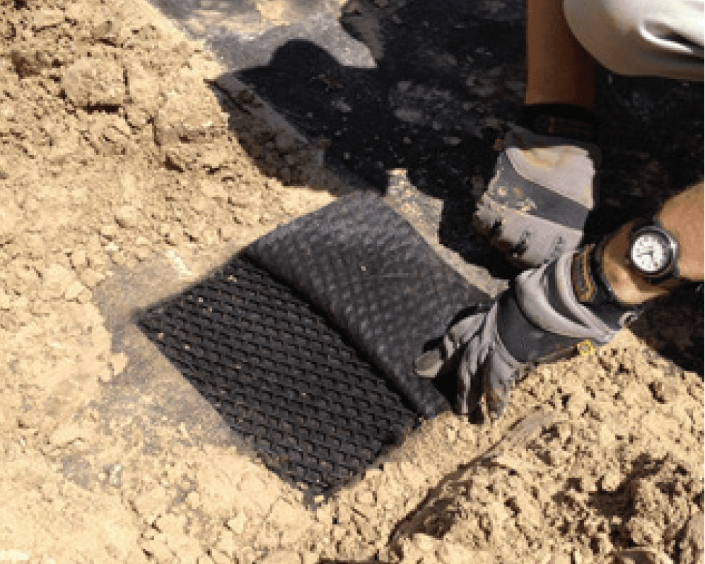
Here, O95 = the filtration opening size (FOS), which is obtained from hydrodynamic sieving, and d85 = particle size in mm, for which 85% of the total soil is finer. In the above expression, O95 must be based on the hydrodynamic test method – not the dry sieving method, which gives erratic results when used with fine dry glass beads. Since the d85 of most fly ash and FGD materials is in the range of 0.04 to 0.07 mm, we see that O95, which is required for geotextile filters, must be within a corresponding range. Standard drainage geocomposites with 6oz. or 8oz. NW-NP geotextiles have an O95 of 0.1 to 0.3 mm and do not meet the filter requirements. However, we have developed a hybrid geotextile, whose properties are shown in Table 2, which has met the filter requirements for fine CCRs in a number of different projects across the USA. A photo of this geotextile, as bonded to a geonet, is presented in Figure 2.
For the fly ash sample, the d85 is 0.07 mm, and for the FGD sample it is 0.05mm. Using the expression O95 < d85, it can be seen that the Solmax hybrid geotextile satisfies the retention criteria for both samples. Most standard geotextiles, whose O95 ranges from 0.1 to 0.3 mm, are too open for these CCRs, and will result in a piping loss of fines through the geotextile. This type of problem has recently been reported by a number of experts, who found that the geotextile they used was too open, and that the resulting soil loss led to the failure of large parts of their projects.
Laboratory performance data
Extensive laboratory performance data has been generated for the Solmax hybrid geotextile, using CCR samples from six different projects. When it comes to filter compatibility, the gradient ratio is the test that is most commonly used by design professionals and researchers. Figure 4 presents typical gradient ratio data (ASTM D 5101) for samples obtained from a single site. The gradient ratio refers to the ratio of the permeability of a soil-geotextile system to that of the soil. A gradient ratio that is much greater than one represents a soil loss, while a value much lower than one indicates clogging. A geotextile is considered compatible with the base material if the gradient ratio is less than 3, and if that value stabilizes over time. The figure shows that the Solmax hybrid geotextile forms a stable filter against the material within a few hours. The data in Figure 4 is representative of the geotextile performance of several different materials. The results are consistent with calculations that were performed for this material that indicated that the CCR and the geotextile are compatible.
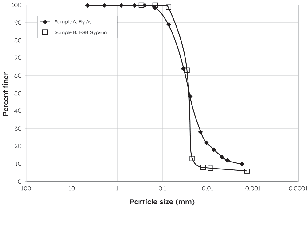
Figure 3: Example gradation of fine CCRs from two projects
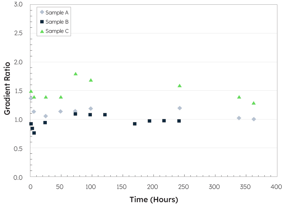
Figure 4 Gradient ratio test on samples of CCRs from a single project
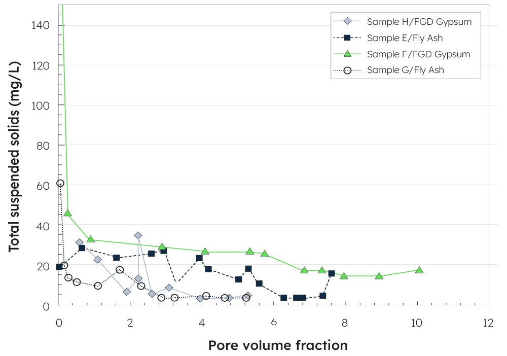
For fine-grained materials like CCRs, a hydraulic conductivity ratio (HCR) test, performed according to ASTM test method D 5567, offers some advantages over a gradient ratio test, since it includes back-pressure saturation, a better stress control, and the use of higher gradients. On account of these advantages, HCR testing was performed on a singlesided FABRINET Coaldrain geocomposite, with the hybrid geotextile facing the fly ash or the FGD gypsum. Typical results from HCR tests performed on fly ash and FGD gypsum, drawn from two projects, are presented in Figure 5.
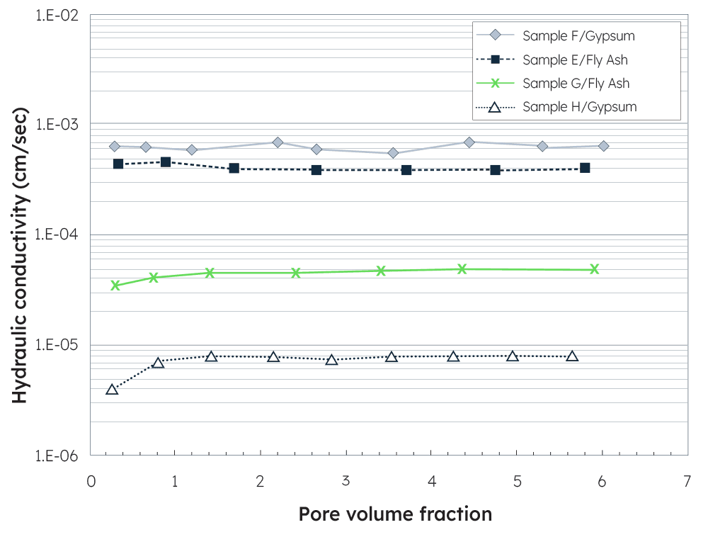
The results are presented in terms of hydraulic conductivity rather than as a ratio in order to illustrate the range of the hydraulic conductivity performance for different types of CCRs. As can be seen in the figure, the geotextile does not inhibit flow and is able to respond differently for each of the samples. Moreover, there is practically no change in hydraulic conductivity with pore volumes which indicates that a stable filter system has been established. Clogging of the geotextile would be indicated by curves that are very close together, with a decrease in the hydraulic conductivity with the pore volumes.
Intermediate-scale field tests
Field tests were conducted at the Olentangy River Wetland Research Park of Ohio State University. Four existing test basins of intermediate size, which are shown in Figure 6, were utilized for the tests.
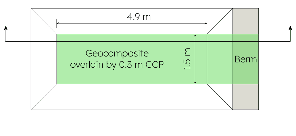
Figure 6(a): Plan view of the test plot
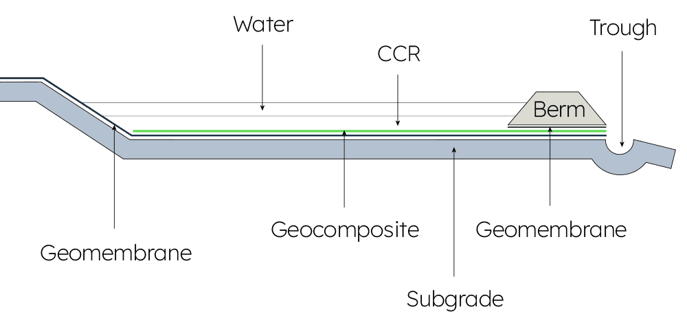
Figure 6(b): Section along the length of the plot
Each of the test basins was approximately 4.9 meters by 1.5 meters and had a side slope of 2H:1V. A 0.6-meter-wide collection trough was placed at one end of each of the basins. The test basins were lined with a geomembrane to ensure that water could exit only through the geocomposite via the collection trough. The geocomposite with the hybrid geotextile facing upwards was installed in the test basins above the geomembrane. The test basins were filled with about 0.3 meters (1 ft) of CCP material. A 2,100-liter (550 gallon) tank was installed at one end of each of the basins to provide water for the testing. The tanks were plumbed sequentially so that about 4,200 liters of water were available for each test basin. To maintain a constant head of water during the testing process, six pore volumes of water were released into each of the test basins at a controlled rate. Staff gauge measurements were taken within the test basin and the collection trough at timed intervals.
Large-scale field tests
A large-scale field test is the ultimate measure of the performance of a product. An independent engineering firm of international repute tested the FABRINET Coaldrain geocomposite under conditions quite similar to those one would expect in a CCR containment project. Three ponds were prepared side-by-side and were lined with a geomembrane. Double-sided FABRINET Coaldrain geocomposite was then installed in two ponds, followed by fly ash in one, and FGD gypsum in the other. In the third pond, coarse bottom ash was used as the drainage layer instead of FABRINET Coaldrain, since this was a locally available product that could be a cost-effective alternative to FABRINET Coaldrain. The same fly ash as was used in one of the two other ponds was placed over the bottom ash in the third pond. All three ponds were then filled with water, and the effluent from the drainage layers was monitored over time.
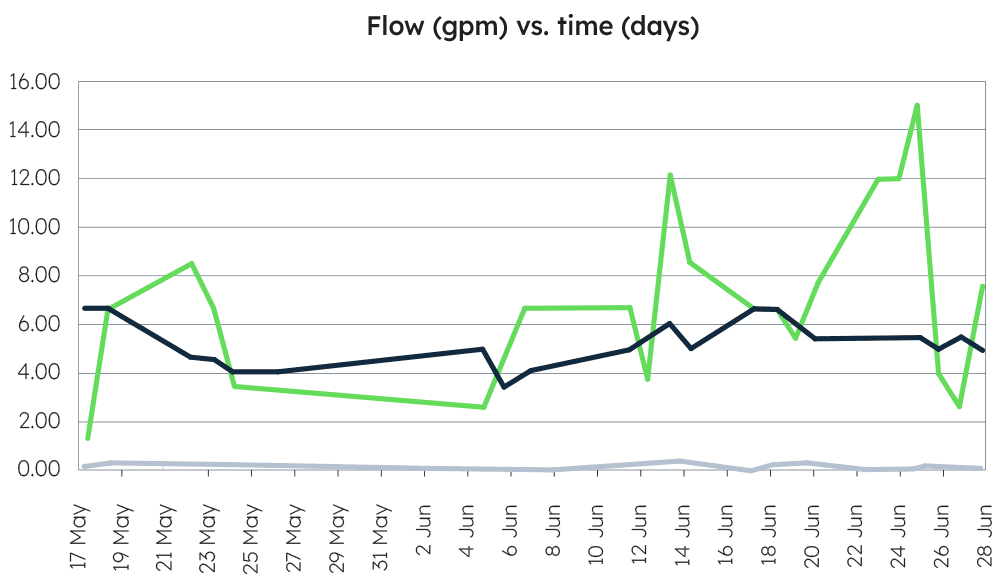
The two cells with FABRINET Coaldrain performed very well, showing insignificant fines in the effluent. Flow rate measurements (Figure 8 showed that the hybrid geotextile overlying the FABRINET Coaldrain geocomposite performed its intended function in both cells.
The third cell, in which FABRINET Coaldrain was not used, not only showed piping of fines in the effluent, but was deemed by the site engineer to be unsuitable for use as a filter and drainage layer. At the end of the test period, the CCR waste was carefully removed from the ponds in order to visually inspect the condition of the FABRINET Coaldrain.
The top hybrid geotextile was cut out in order to expose the geonet core and any fines that had accumulated within it. Practically no fines were found within the geonet core. Transmissivity tests performed on the retrieved material showed that there had been no loss of hydraulic performance over the time period of exposure in the project. Figure 9 shows a photo of the exposed geocomposite after the overlying geotextile was removed.
References
Butalia, T.S., “CCP in Constructed Landfills: Characteristics, Beneficial Use, Disposal & Impact on Geocomposite Leachate Collection Systems”, GSE Technical Seminar, 18 October 2012, Chantilly, VA.
Schmitt, N. & Cole, B., “Evaluation of Drainage Layer Alternatives for Proposed CCP Landfill Liner”, GSE Technical Seminar, 18 October 2012, Chantilly, VA.