Overview
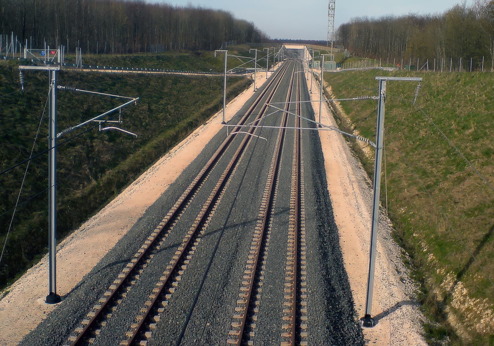
The high-speed LGV railway connection between Paris, Bratislava and Budapest constitutes a 1,500 km long railway corridor of major European importance. In France, the LGV East connects Paris to Strasbourg, and it will then continue on into Germany and then onto the Czech Republic and Slovakia. The first phase of the LGV East from Paris to Baudrecourt was completed in 2007. The second phase from Baudrecourt to Vendenheim, near Strasbourg, began in 2010. In 2011, on section 42 near Sarrebourg, foundation subsidence was observed during preliminary earthworks along the railway alignment.
Challenge
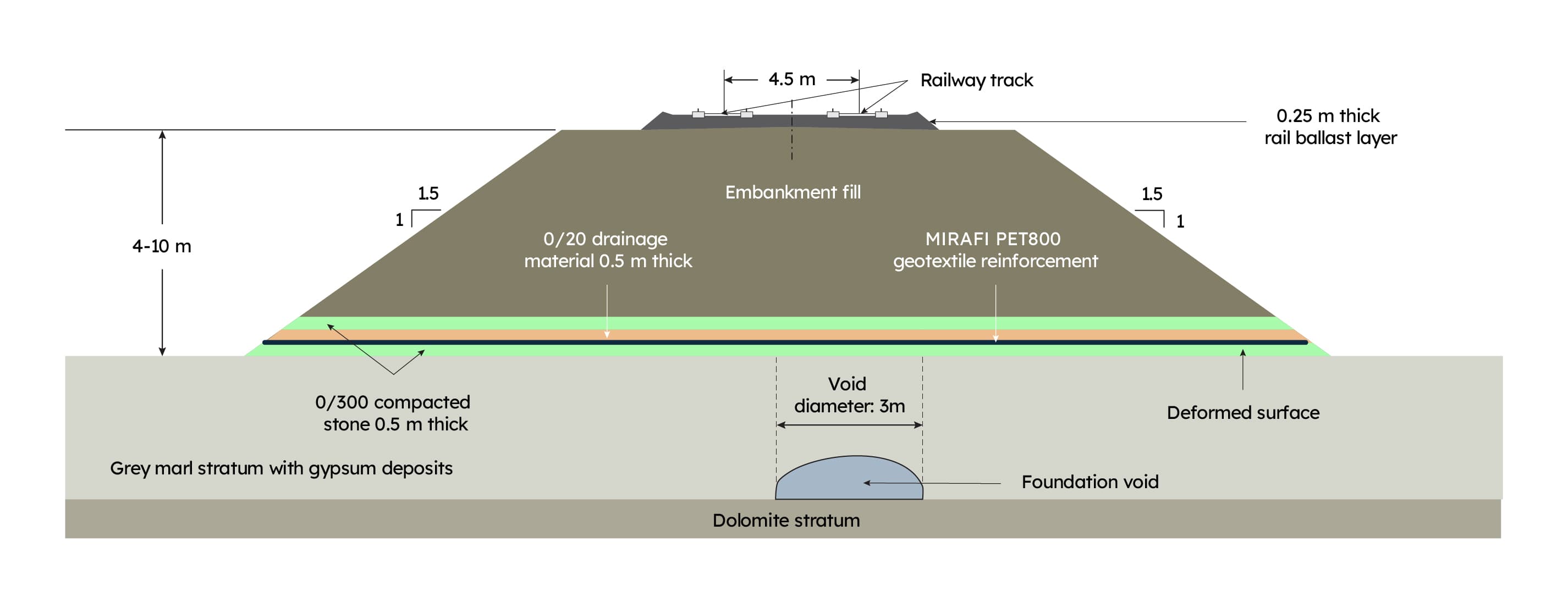
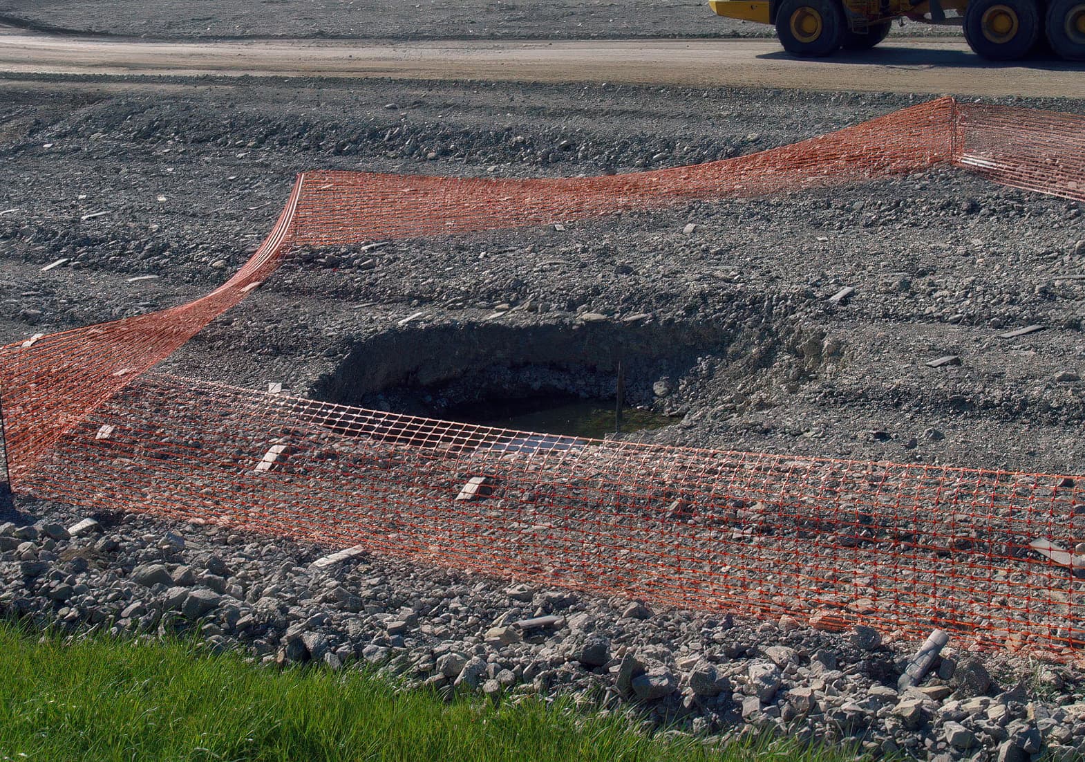
At the foundation surface, voids of 3 m diameter were observed where an embankment varying in height up to 10 m was to be constructed. The geology of the area displays a thin layer of silt at ground surface, under which lies a stratum of over consolidated marls with agglomerations of gypsum throughout. Below this is a stratum of dolomite. Most of the gypsum deposition is located immediately above the dolomite stratum, and due to the presence of groundwater the gypsum has been dissolved, leaving voids in many locations above the dolomite stratum. The presence of these subterranean voids has resulted in subsidence at the ground surface in many locations. To prevent the detrimental effects of foundation subsidence and differential deformations propagating up through the embankment fill and impacting the performance of the rail track structure, it was decided to install a combination of highly granular layers (φ’ > 43 degrees) and geotextile reinforcement across the base of the embankment.
Solution
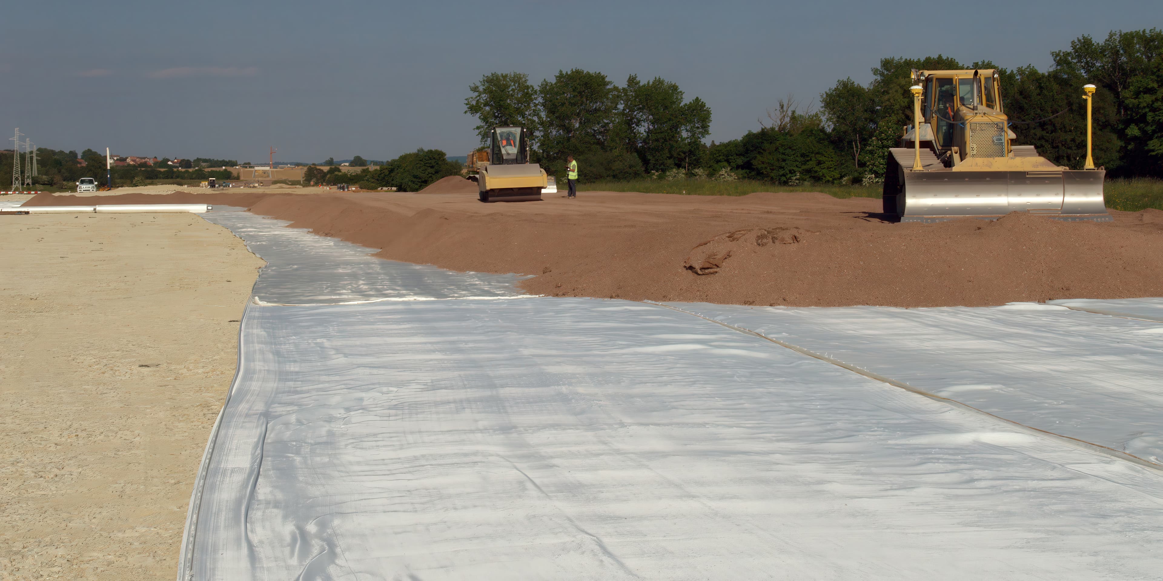
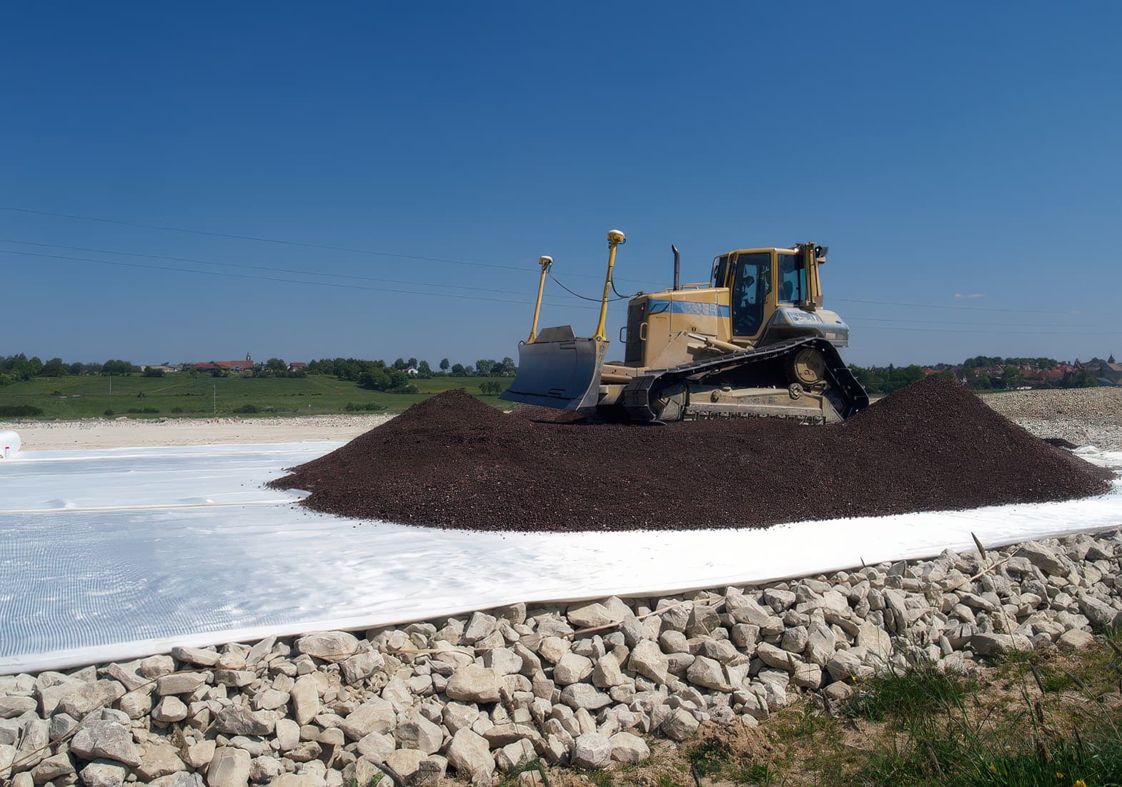
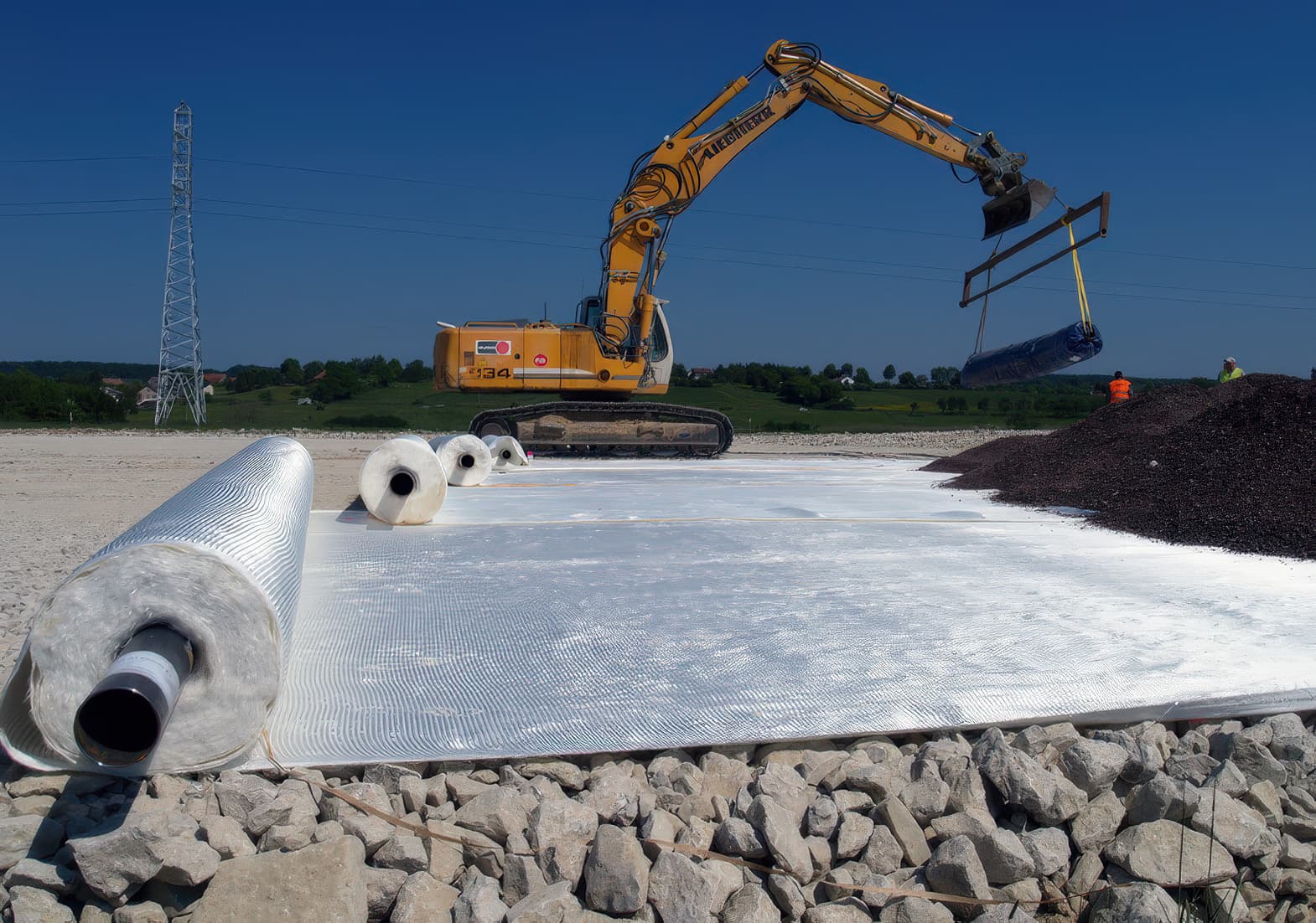
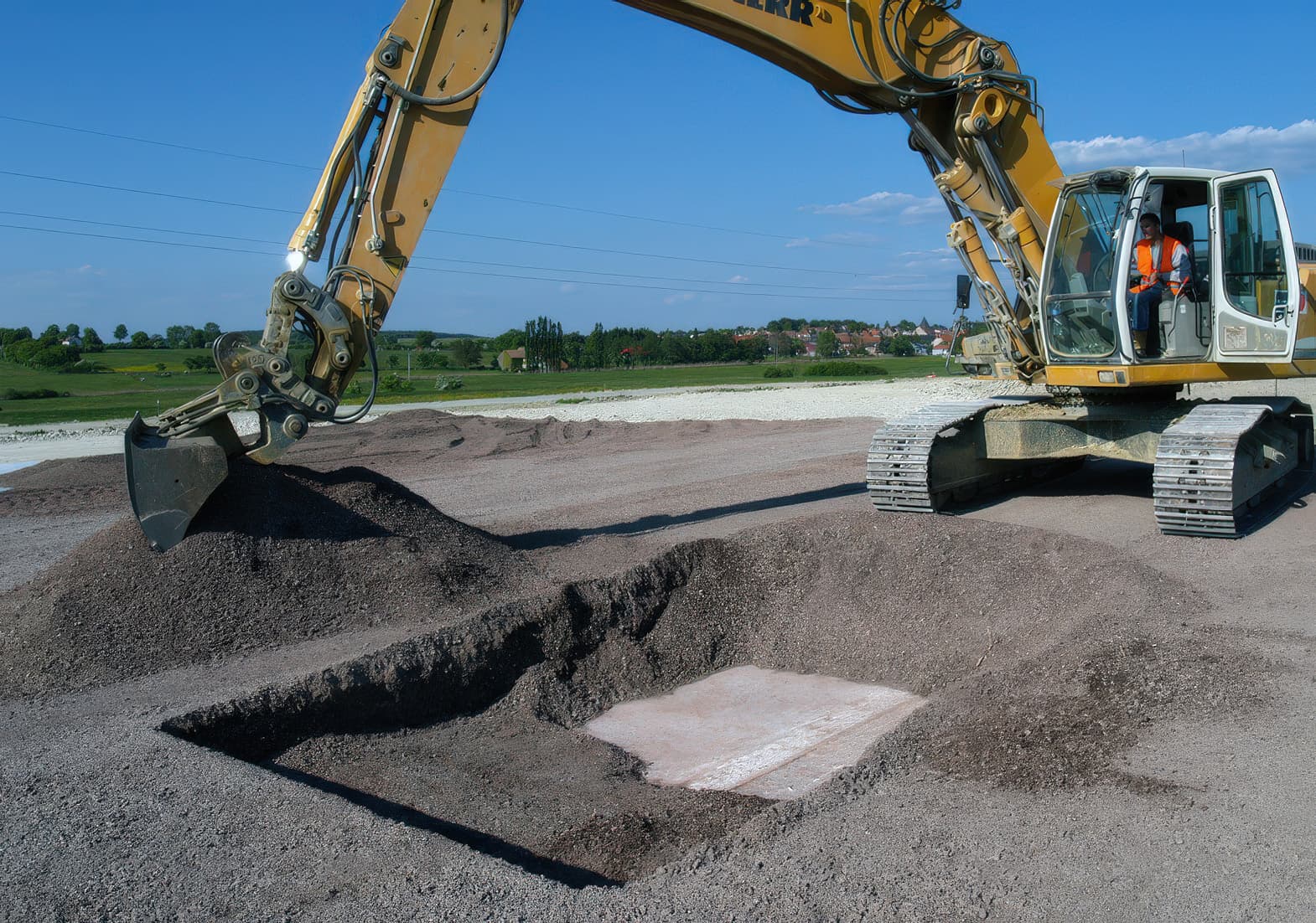
The granular layers consisted of 0/300 mm stone sizes and were compacted into layers 0.5 m thick. These layers had high dilatancy and so would be expected to provide good resistance to any subsequent vertical deformations arising at the base of the embankment. The geotextile reinforcement sandwiched within this granular layer system was MIRAFI® Geolon PET800 geotextile reinforcement (initial tensile strength 800 kN/m), which provided the tensile strength and stiffness to maintain serviceable conditions at the base of the embankment. A 0/20 mm gravel drainage blanket of 0.5 m thickness immediately on top of the MIRAFI Geolon PET800 geotextile reinforcement was used as protection for the geotextile. For the design of the basal reinforced embankment system, a design void diameter of 3 m was assumed, as this was considered representative of the subsidence that would occur at the base of the embankment. The design analysis was carried out using the RAFAEL method, which assumes a cylindrical failure at the sides of the void along with associated soil relaxation. The maximum deflection of the geosynthetic reinforcement under these conditions and then the allowable deformation is a function of the settlement at the ground surface. The RAFAEL analysis showed that to meet the embankment surface deformation limits, the maximum tensile strain in the basal geotextile reinforcement should be limited to < 5% over a 100-year design life. The use of MIRAFI Geolon PET800 geotextile reinforcement satisfied this criterion. The foundation preparation works involved a survey of cavities along the railway embankment alignment. In zones where there was a high concentration of cavities, it was planned to fill the voids by injection grouting after the embankment had been constructed. In the remaining areas, it was planned to rely on the basal reinforcement for spanning any future subsidence. After the MIRAFI Geolon PET800 geotextile reinforcement had been unrolled over the 0/300 mm compacted stone layer at the base of the embankment, a 0/20 mm gravel drainage blanket was spread on top and compacted to 0.5 m thickness. The purpose of the drainage blanket was to provide protection to the MIRAFI Geolon PET800 geotextile prior to placement of a further 0/300 mm compacted stone layer. Following compaction of this drainage layer, a trench was excavated in order to allow visual inspection of the geosynthetic reinforcement. It was observed that there was negligible apparent damage to the geosynthetic reinforcement. Following the placement of the basal granular layers and geotextile reinforcement, the construction of the embankment was completed, with the railway structure constructed on top.