Overview
The Wat Nakorn-In Bridge and connecting road system is a major infrastructure project, and is part of a larger master plan to ease traffic congestion on the West bank of the Chao Phraya River in the Greater Bangkok area. The new bridge crosses the Chao Phraya River midway between the Rama VII and Nonthaburi bridges. The project also involved a network of connecting roads that necessitated the construction of other smaller bridges and traffic overpasses. Because of the overall project size, the project was awarded in five contracts, each involving the construction of bridges and embankments to handle up to 10 traffic lanes. The foundations in the area consist of what is known as “soft Bangkok clay”, overlying a stiff clay layer. This soft clay layer has a thickness of about 15 m to 20 m in the Bangkok metropolitan area. Bangkok clay has low shear strength, and is highly compressible, as it is close to being normally consolidated. Typically, the soft Bangkok clay layer has water contents ranging from 80% to 140%, undrained shear strengths from 6 kPa to 15 kPa and bulk densities of 14 kN/m3 to 16 kN/m3.
Challenge
Consolidation of the soft clay can lead to large differential settlements between embankments constructed directly on the clay, and any piled bridge structures. These differential settlements reduce riding quality and pose safety hazards. They also involve frequent maintenance works, which prove costly over time and cause unnecessary traffic disruption during the maintenance works. The embankments approaching the Wat Nakorn-In Bridge were designed with pile support to provide stability as well as to prevent large differential settlements between the embankments and the bridge structures.
Solution
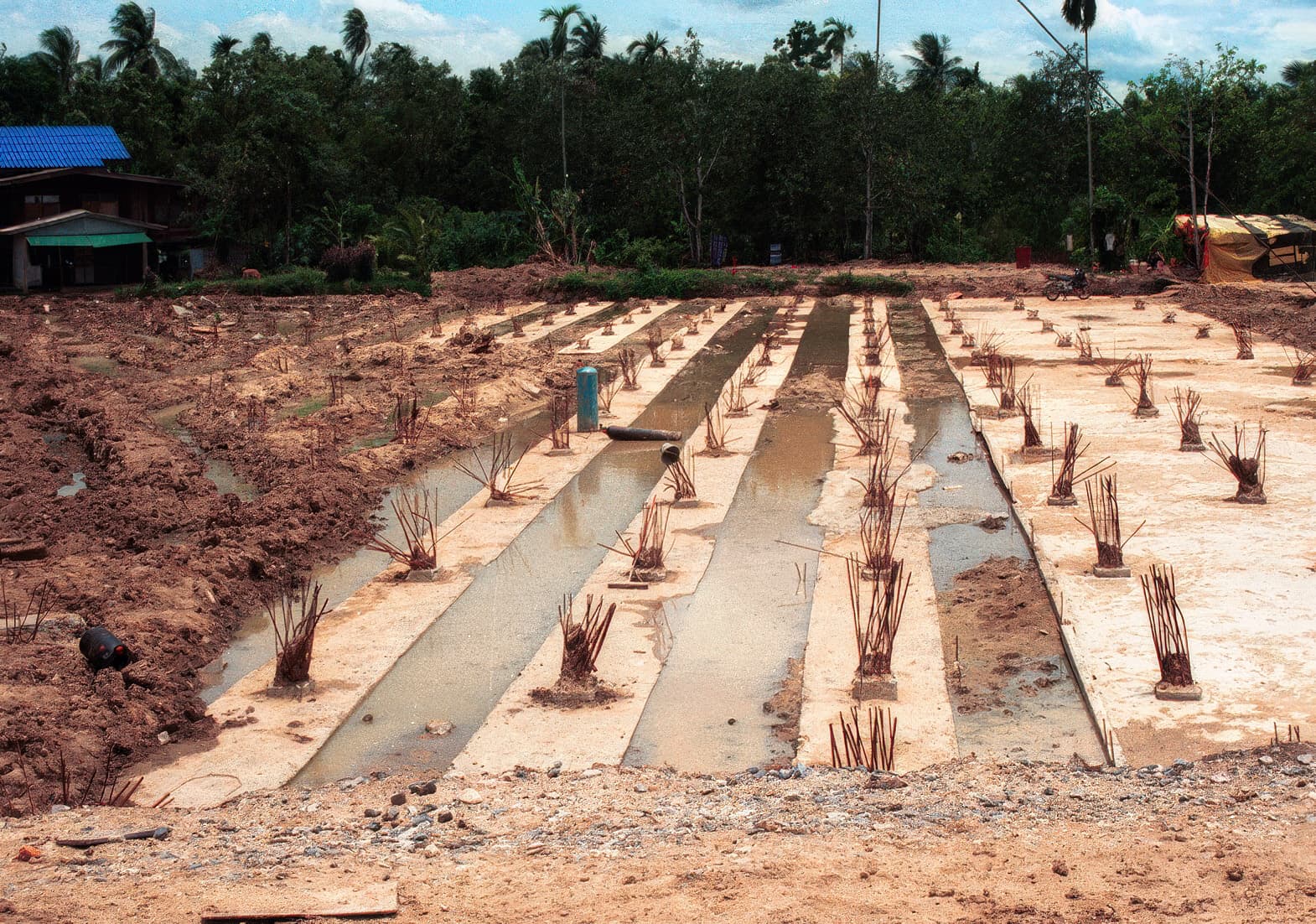
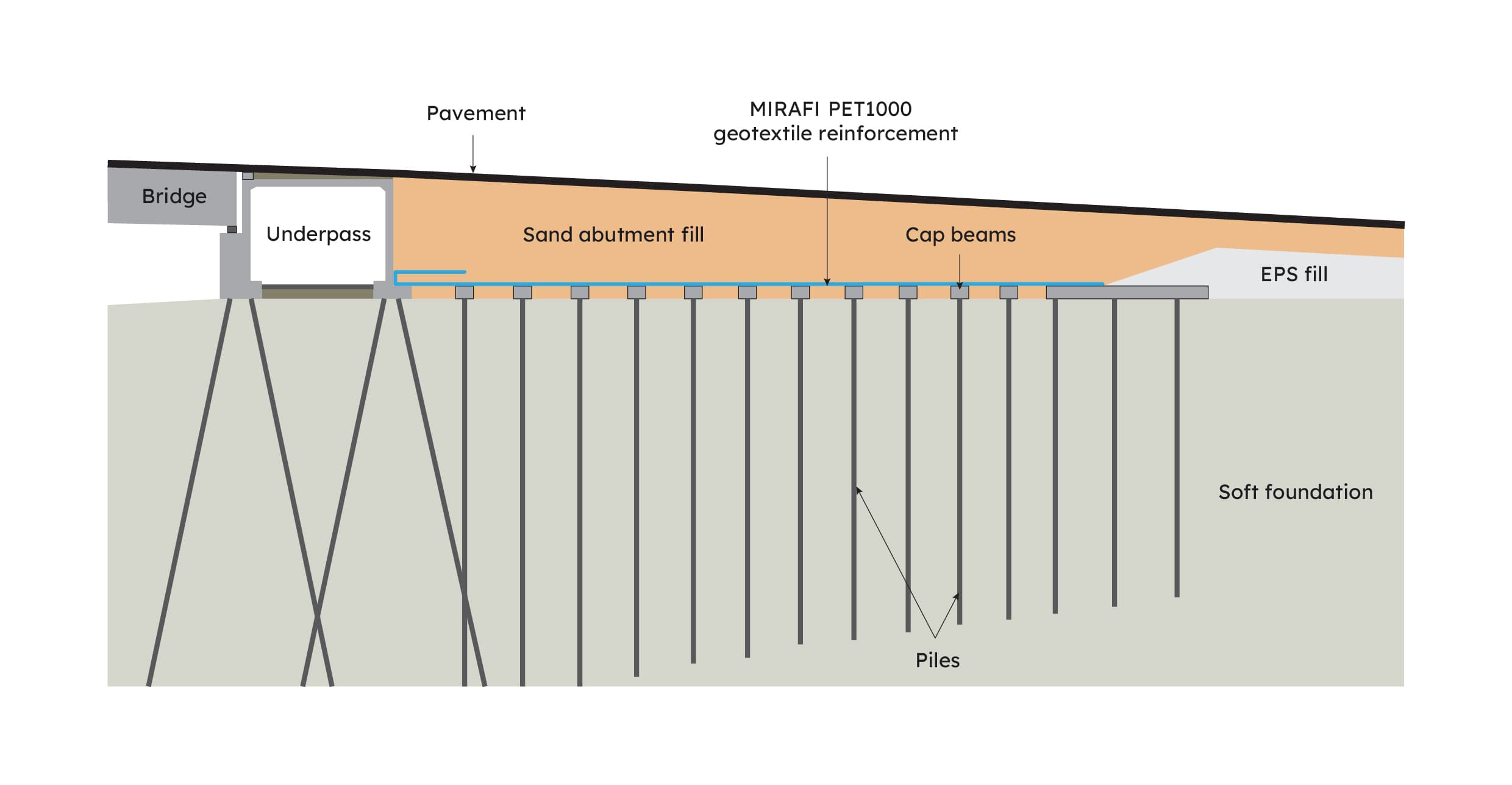
The pile lengths were gradually increased as the embankment heights increased and as the embankments approached the bridges. Where the embankments met the bridge structures, the piles supporting the embankments were designed for end-bearing, similar to those supporting the bridge structures. This tapering of pile depth ensured a smooth road profile transitioning from the section unsupported by piles, over the entire embankment sections supported on piles, and across the bridge structures. At the beginning of construction, all surface vegetation was removed from the site. Precast reinforced concrete piles, 100 mm square, were driven to the design depths using drop hammer piling machines. Beneath the embankments the spacing between these piles ranged from 1 m to 2 m depending on the distance from the bridge. Pile caps and connecting beams were then constructed on top of the piles. Connecting beams were included because the foundation soil was very soft and it was thought that additional lateral restraint was required for stability purposes.
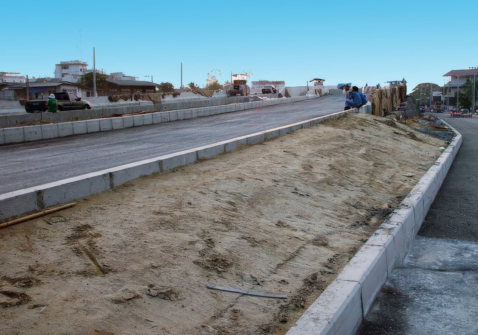
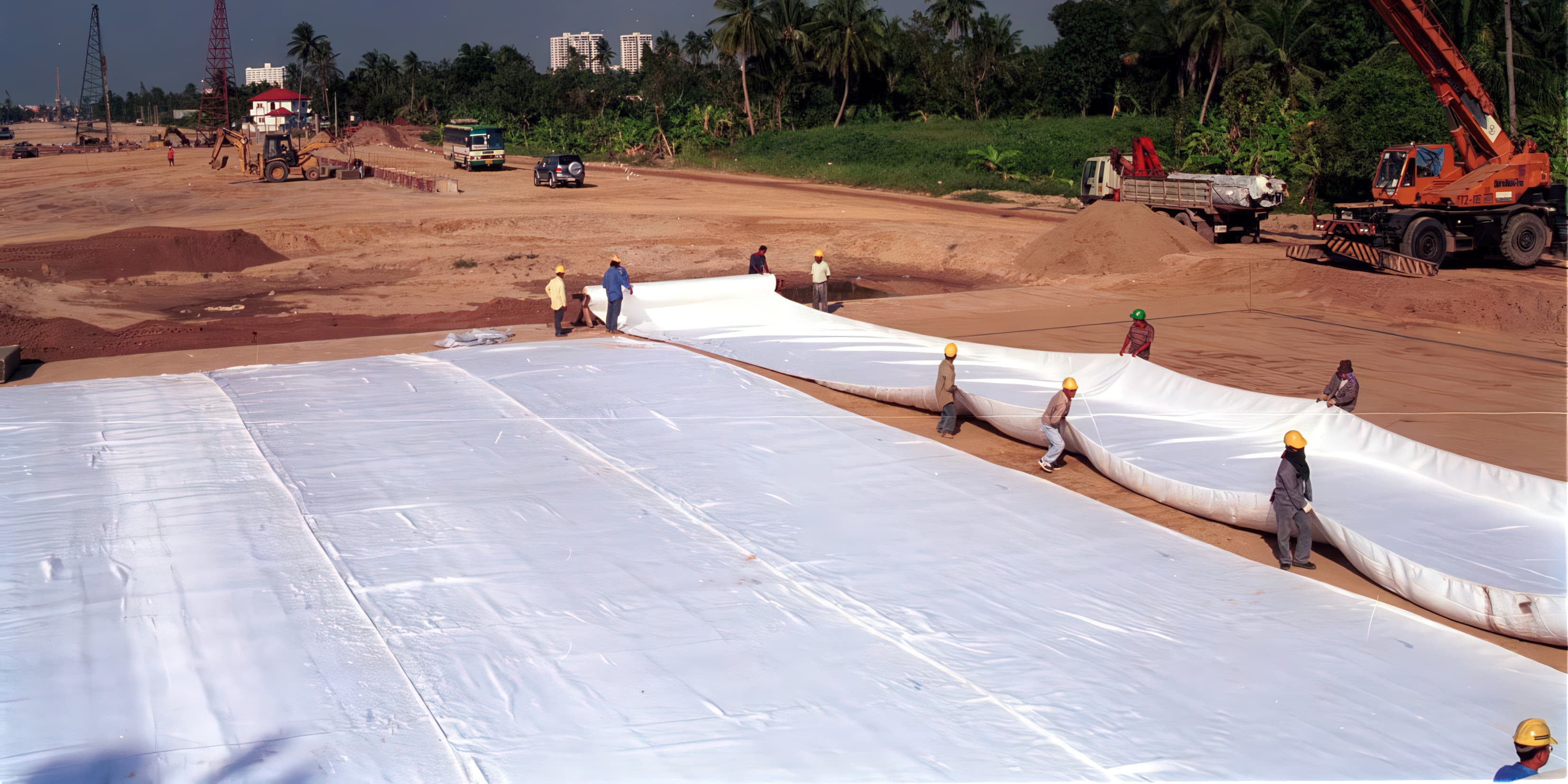
This was followed by backfilling between the pile caps and connecting beams with sand to form a smooth platform. MIRAFI® PET 1000-100 geotextile reinforcement, which has a tensile strength of 1,000 kN/m in the machine direction and 100 kN/m in the cross direction, was laid over this prepared smooth platform. The MIRAFI PET 1000-100 geotextile reinforcement is designed to span across the pile caps and transfer the vertical embankment and traffic loads directly onto them. In the application, the use of MIRAFI PET geotextile reinforcement ensures negligible load is carried directly by the soft foundation, and all load is carried directly by the piles. The embankments were then constructed by placing and compacting sand fill to the required design heights.
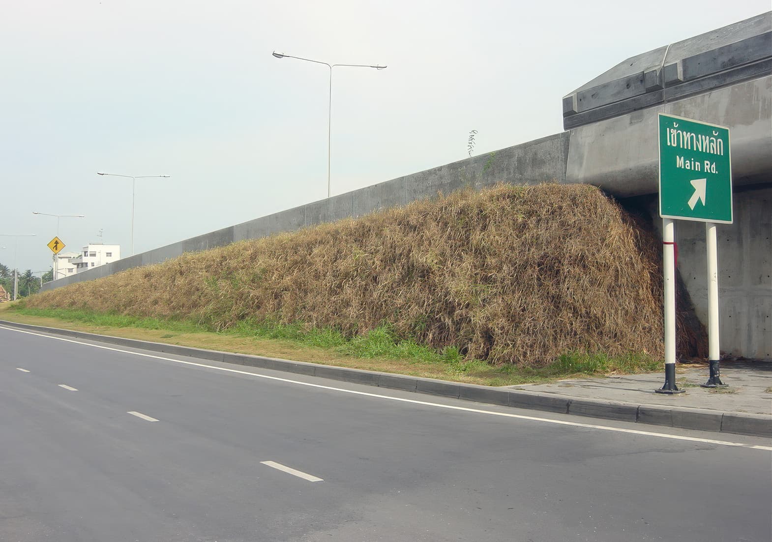
Right-of-way traffic restrictions meant that the embankments had to be constructed with steep side slopes in the vicinity of the bridge abutments. These steep slopes were constructed using MIRAGRID® 5XT geogrid reinforcement at 0.5 m vertical spacings. The surface of the reinforced steep slope was then vegetated to provide a green finish to the embankment sides. In other areas where the embankment heights were low and differential settlements were not an issue, expanded polystyrene (EPS) fill was used to construct embankments of low unit weight. This reduced the level of settlements occurring in these embankments. Once the embankment earthworks had been constructed the pavements were constructed on top. Flexible asphalt pavements were used throughout.