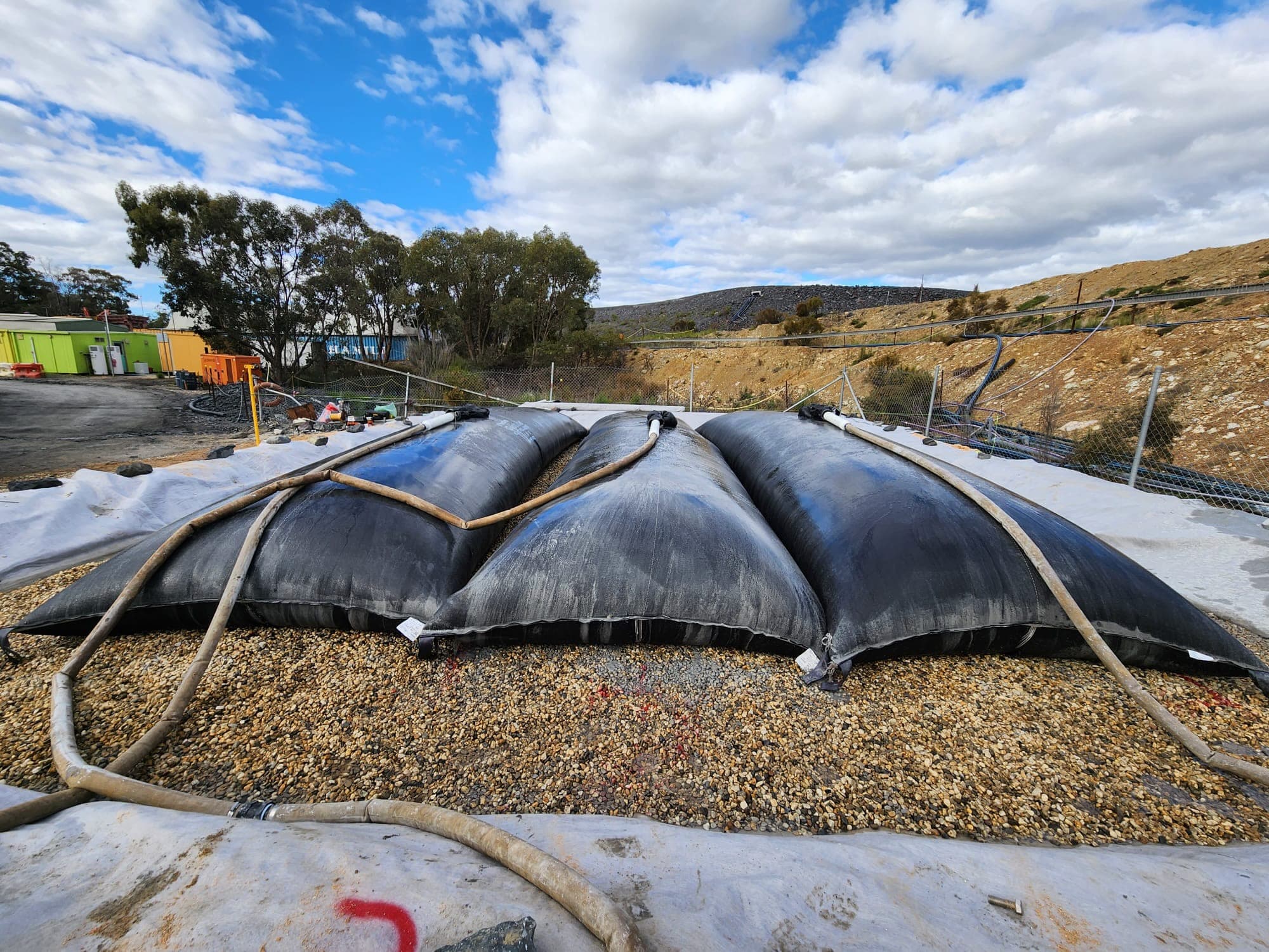
How can mining companies effectively manage dewatering challenges and implement innovative solutions for mine waste management?
When geosynthetic reinforcement is installed and the backfill material is compacted against it, a loss in initial strength can occur. This reduction in strength due to installation damage is addressed by using a material reduction factor, known as fid. The value of fid is influenced by both the reinforcement structure and the type of backfill material used. Typically, installation damage tests are conducted on-site, following standardized methods like ASTM D5818 or BS8006-1:2010 Annex D, with a variety of backfill materials.
Unlike other material reduction factors, such as those accounting for creep or durability – which are time-dependent – installation damage is an immediate effect. The reduction in strength occurs during the construction phase, with little to no further degradation over time. Thus, it is generally treated as a time-independent factor.
The choice of backfill materials hinges on several factors:
Application Type: For example, a reinforced soil wall with segmental concrete blocks often requires frictional fill, whereas embankments can allow cohesive frictional fill.
Design Standards: The selected materials must meet specific requirements outlined by design codes or relevant authorities.
Availability: The selection is often influenced by local conditions. For instance, remote areas might have limited backfill options compared to urban settings.
Project Economics: Budget constraints can also play a significant role in material selection.
Based on these considerations, engineers select the most suitable backfill material. Since different particle sizes in backfill can impact the intensity of damage on the reinforcement, manufacturers should ensure their products are tested against a range of backfill materials. Below is a typical classification of backfill materials used in the construction industry:
Table 1: Typical backfill materials
Types | Max. Particle Size (mm) | Typical applications1 |
Gravel | 125 or more | Marine construction (e.g. seawall), heavy-duty working platform stabilization, etc. |
Gravel/ aggregate | 50 | Load transfer platforms, reinforced soil walls, landfill construction, etc. |
Sand and cohesive fill (clay, silt) | 2 | Embankment construction, reinforced soil slopes, etc. |
1 Typical application serve as a general reference only, the engineer’s specification on each project takes precedence.
It is crucial to note that projects may involve multiple grades within a product line, making comprehensive testing for each grade impractical. In such cases, testing a few representative grades is advisable. For untested grades, engineers can either conservatively apply reduction factors from lower-grade tests or interpolate between the grades (or backfill material particle sizes if needed).
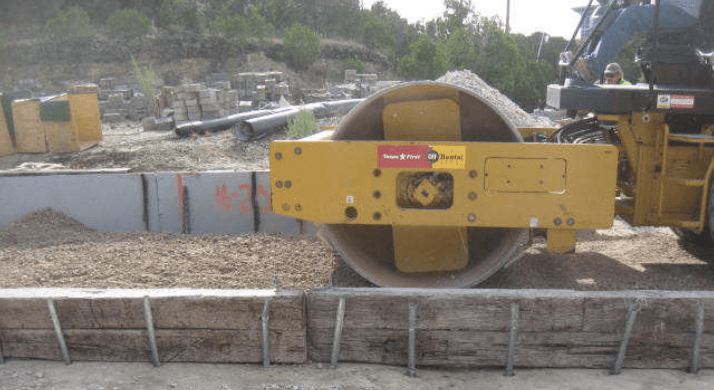
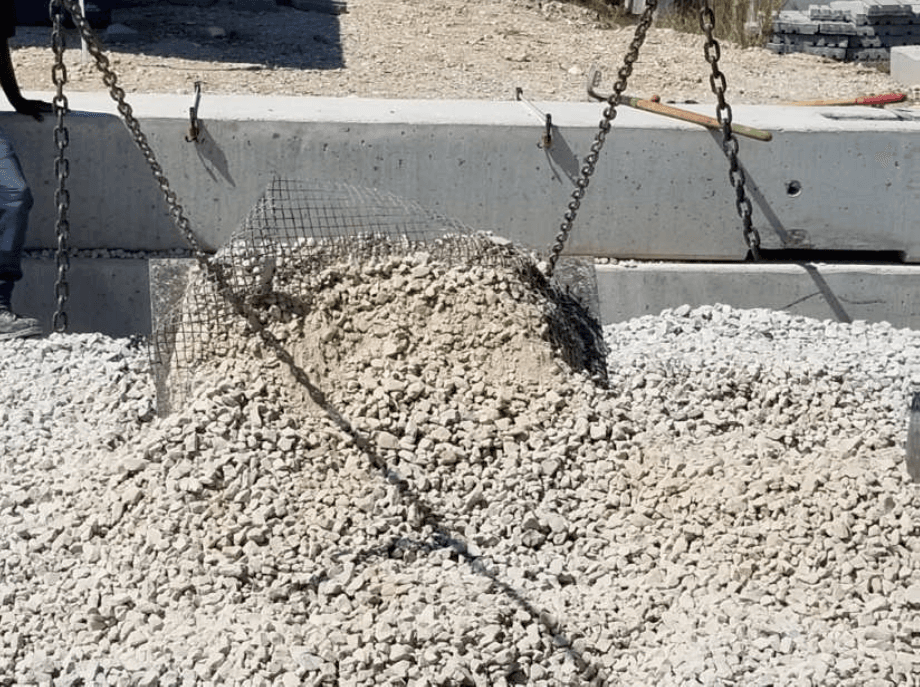
Installation damage testing is best conducted on-site, following established guidelines like BS8006 Annex D or ASTM D5818. Steps below explained the typical test sequence (TRI, 2020):
1. Positioning of lifting plates: Plates are strategically placed between ties.
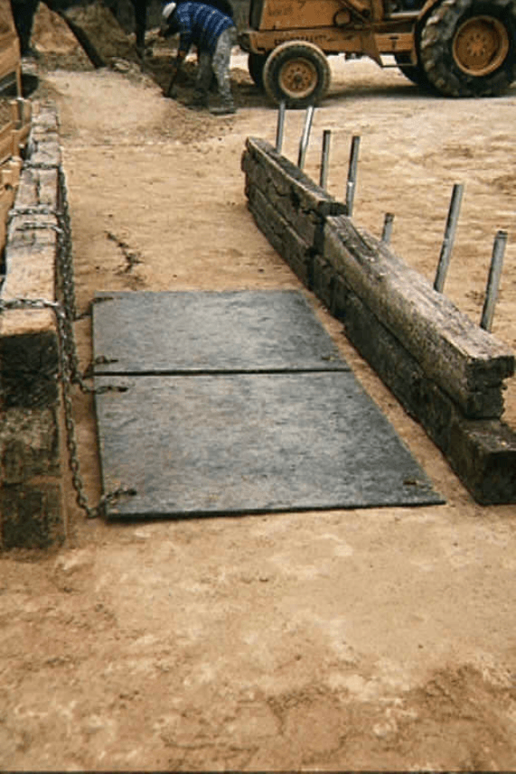
2. Compaction of the initial soil layer: A soil layer is compacted below the reinforcement.
3. Laying of reinforcement: The geosynthetic reinforcement is positioned over the compacted soil.
4. Compaction above reinforcement: A second layer of soil is compacted over the reinforcement.
5. Exhumation and tensile testing: The reinforcement is excavated for tensile strength testing.
In the geosynthetics industry, it is a well-accepted principle that only on-site test results are valid for deriving the material reduction factor fid. Laboratory methods, such as ISO 10722, may serve as internal benchmarks for manufacturers, but they should not be relied upon for calculating fid.
The installation damage resistance of geogrids and geotextiles is a critical aspect of construction with geosynthetics. Proper selection of backfill materials and accurate assessment of the material reduction factor fid ensure the longevity and effectiveness of reinforced structures. On-site testing remains the most reliable method to determine this reduction factor, reflecting real-world conditions that laboratory tests cannot replicate. By adhering to these practices, engineers and manufacturers can ensure that geosynthetic installations are both robust and resilient, supporting the infrastructure they are designed to reinforce.
AASHTO R69-15 (2015). ‘Standard practice for determination of long-term strength for geosynthetic reinforcement’. Washington D.C.: American Association of State Highway and Transportation Officials.
ASTM D5818-11:2018. ‘Standard practice for exposure and retrieval of samples to evaluate installation damage of geosynthetics’. Pennsylvania: American Society for Testing and Materials.
BS8006-1:2010. ‘Code of practice for strengthened/ reinforced soils and other fills’. London: British Standards Institution.
FHWA (2001) ‘FHWA-NHI-00-043 Mechanically stabilized earth walls and reinforced soil slopes design and construction guidelines’. Washington D.C.: Federal Highway Administration.
TRI (2020) ‘Installation damage testing of MIRAGRID GX Geogrids GX40/40, GX60/30, GX80/30, GX160/50 (Revised April 1, 2021)’. Texas: TRI Environmental.